Mfr Part # 11367
HOOK-UP WIRE ASSORT SOLID 22AWG
SparkFun Electronics
License: See Original Project ADCs Hall Effect
Courtesy of SparkFun
Guide by Alex the Giant
Introduction
Let there be light! In this tutorial we'll build a basic magnetic levitator. This guide will go over some of the theory, how to use a magnetic field sensor, and how to use one to build a basic levitation circuit. Finally, we'll go a bit further and build a wireless power floating light.
Required Materials
To follow along with the examples in this tutorial you will need the following materials:
Magnetic Levitation Tutorial
Capacitor Ceramic 0.1uF
Heads up! The LM358 is scheduled for EOL. We recommend the AS358 as a drop-in replacement as the general-purpose op-amp. The part is compatible with the 358.
The other parts used that we don't carry are:
Analog Hall Effect Sensor
1N5401 Diode
1mH Inductor
Required tools
The tools needed for this project is a multimeter and soldering iron, but having access to an oscilloscope will help with testing as well.
Suggested Reading
If you aren’t familiar with the following concepts, we recommend checking out these tutorials before continuing.
How to Solder: Through-Hole Soldering: This tutorial covers everything you need to know about through-hole soldering.
How to Use a Breadboard: Welcome to the wonderful world of breadboards. Here we will learn what a breadboard is and how to use one to build your very first circuit.
How to Use a Multimeter: Learn the basics of using a multimeter to measure continuity, voltage, resistance and current.
Introduction to Operational Amplifiers with LTSpice: Picking up where we left off in "Getting Started with LTSpice," we delve a little deeper into LTSpice through an introduction of Operational Amplifiers (OpAmps).
Theory Basics
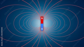
When it comes to magnetic levitation, there are two kinds of levitation: attractive and repulsive. In this guide, we're going to use an attractive levitation circuit as it's a lot easier to get working. As we know, a magnet has two poles, north and south. Magnetic fields with the same polarity repel each other, whereas opposite poles attract. With magnetic levitation we need a fixed magnetic field, provided by permanent magnets, and a magnetic field that we can control to position the permanent magnets.
Image courtesy of Geek3 via Wikipedia, CC BY-SA 3.0
To create a magnetic field that can be controlled, we can use an inductor. Inductors store energy similar to capacitors; while capacitors store voltage in the form of an electric field, inductors store current by generating a magnetic field. Here we'll be using the magnetic field of an inductor to interact with the magnets. With attractive levitation the inductor is used to oppose the force of gravity which then attracts the magnet up to the inductor.
If the magnet gets too close to the inductor, the magnet's field strength will be strong enough to stick to the inductor, regardless of how much current is passing through the inductor. However, if the magnet is too far away from the inductor, the magnetic field strengths will be too weak relative to gravity to be pulled back up. So, the trick is to find the window where magnet isn't strong enough to pull itself up on its own, but with the attraction of the inductor's opposing field the magnet is able to overcome gravity. To keep track of its position, we'll use a magnetic field sensor, called a hall effect sensor.
Hall Effect Sensor
A hall effect sensor is a device that is used to measure the strength of a magnetic field. The output of the sensor is directly proportional to the magnetic field strength passing through it. The sensor we'll need is the SS496B, which has an analog voltage output. There are other hall effect sensors that act as a switch and only turn on or off in the presence of a magnetic field. In the next section we'll see how the sensor responds to the presence of our magnets.
Testing The Hall Effect Sensor
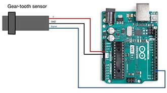
Let's first test to see how the sensor works. With a breadboard, connect 5V to the supply voltage pin, ground to ground, and on the output pin, connect either an oscilloscope probe to watch the voltage change, or we can use a multimeter in voltage mode to watch the voltage change.
Without a magnet present, the output voltage sits at around 2.5V. With one side of the magnet, as the magnet gets closer to the sensor, the voltage decreases. If you flip the magnet around and bring it closer to the sensor, you'll see output voltage increase. Make note of which side causes the voltage to decrease. It might help to make a mark with a permanent marker, which will be useful in our next test.
Note: The magnets used in the photos are round, measuring around 0.5 inches in diameter and 0.1 inches in height, but the square magnets will work as well. What's important is that they are neodymium (otherwise known as rare earth) magnets.
Before moving on to the next test, however, we'll need to extend the leads of our sensor by adding some wire. It's a good idea to add heat shrink tubing around each of the solder joints to make sure they don't short together, but a little bit of electrical tape around the leads will work as well. In the image below, the sensor has a red wire for the positive voltage supply, black for the negative, and yellow wire for the analog output.
While the soldering iron is hot, now is also a good time solder wire to the inductor as well. Using different colors for the two pins of the inductor may help with troubleshooting later on.
Building The Control Circuit
As mentioned in the Theory Basics, it's important that the magnet is positioned close enough to the inductor's magnetic field that it is able to interact with the magnet, but not so close that the magnet's own magnetic field is able to pull itself up to the inductor regardless of the power. What we need is a way to control the inductor so that when the magnet is too far away, the inductor will pull the magnet closer, but turn off when it gets too close, so that gravity can still pull it back down.
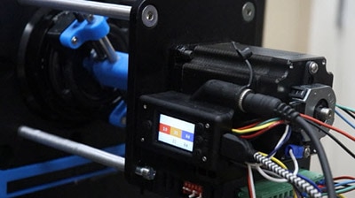
Before we start wiring up electronics, a stand has to be made to hold the inductor above the ground. This guide isn't going to go over making a stand but below is a photo of the stand used for reference. The inductor hangs about 5 inches above the table, and a 8-32 bolt (~1.5 inches in length) and nut are used to attach the inductor to the stand.
Tip: Make sure a magnet can stick to the bolt. The ferrous material of the bolt will "focus" the magnetic field lines on the inductor and the magnet will be pulled up to the center of inductor.
Once the inductor is mounted, we'll need to attach the hall effect sensor to the head of the bolt. If there's any exposed metal from the sensor, use a piece of electrical tape to insulate the sensor from the bolt and secure the sensor with more electrical tape as shown below. Note that the curved side of the sensor is facing away from the inductor.
The Comparator Circuit
To control the inductor, we're going to use an op-amp in a configuration called a comparator, which compares the output of the hall effect sensor to a reference voltage that is connected to the other input pin. The reference voltage is set with a potentiometer acting as a voltage divider - this creates an adjustable analog voltage between 0V and 5V. The voltage of the potentiometer represents what voltage we want the hall effect sensor to read, which is based on how far away the magnet is.
This circuit uses two voltage rails, 5V and 12V. The 12V rail is powering the inductor and op-amp, and the 5V rail is used for the voltage reference and hall effect sensor. Two power supplies are ideal, because if the 12V rail goes into current limiting mode, and the voltage drops, the hall effect sensor won't have a high enough voltage to detect when the magnet is close enough. You can, however, get away with a single power supply rail using a LM7805 linear voltage regulator. If you plan on using two power supplies, make sure you connect the grounds together, otherwise the circuit won't work correctly.
Note: The schematic lists U2 as a SS494, but the SS496 should be used as it has greater sensitivity, but the pinout is the same.
Schematic of Comparator Circuit
Fritzing Image of Comparator Circuit
Once the circuit is built, we'll use a multimeter to measure the voltage at the non-inverting input (pin 2 of the op-amp) and turn the knob on the potentiometer until it reads 0V. Next, we'll position the magnet about 2cm away from the sensor, or about a thumb's thickness. Essentially, the magnet needs to be in the "sweet spot" - a position a bit further away than the position where the magnet wants to pull up on its own and stick to the inductor.
Looking at the output voltage of the op-amp (pin 1), it should be reading 9-12V. With the magnet still in position, we're going to slowly turn the potentiometer and increase the reference voltage until we see the voltage change from 12V to 0V. Moving the magnet up and down a little should change the output of the op-amp from high to low and low to high.
The comparator is trying to keep the voltages between the input pins equal and driving the output high or low so that the sensor value matches the reference value. In the next step we'll attach our inductor to the output of the op-amp and try to make a magnet levitate!
Levitating A Magnet
Now that we understand how the comparator is going to control the inductor, let's try and levitate a magnet. Op-amps are good at controlling signals, but for larger current applications like this, we'll need to use a mosfet. Turn off power to the circuit we built in the last section and wire up the following circuit. Make sure not to skip the diode! When an inductor switches off, the magnetic field it created collapses, which can cause a large voltage spike, and may damage the mosfet. The schematic lists a 1N4007 diode, but the 1N5401 diode should work better with flyback current spikes.
Note: The schematic lists U2 as a SS494, but the SS496 should be used as it has greater sensitivity, but the pinout is the same.
Schematic of Comparator Circuit with The Inductor
Fritzing Image of The Comparator Circuit with The Inductor
With the power still off, turn the potentiometer’s knob all the way to one side, such that the reference voltage is set to 5V. Next, turn the power on and verify that the output of the op-amp is reading 0V. Position the magnets between your thumb and middle finger, as shown below. Your thumb will be able to catch the magnet if it gets pulled up to the inductor, and your middle finger is there to balance the magnets and catch them if the magnets fall.
With your other hand, slowly decrease the reference voltage. As you get close to the transition point from the Building the Control Circuit, the magnets should start to levitate. If the magnets jump up to your thumb, increase the voltage again, and then try again. With some practice and small but precise movements, the magnets should be able to levitate.
Tip: If the magnet tries to flip over such that the mark on the magnets is pointing away from the inductor, the magnetic fields are the same and repelling each other. Reversing the wiring for the inductor will fix this problem.
Being able to read the current from the 12V power supply is a good way to see where the levitation point is. When the magnet is too close, the current should be less than 10mA. With the magnets I'm using, the amount of current being used is around 80mA and I'm able to levitate in a window of 2-3cm from the inductor. With a little bit of practice, you should be able to get your magnets to levitate too!
Wireless Power
If levitating a magnet isn't cool enough, you can add even more complexity by adding a wirelessly powered LED. This step requires a few more tools that not everyone has. For this section you'll need the following:
Wireless Power Wish List
Large Heatsink - Multiwatt Package
(2) Capacitor Ceramic 0.1uF
Frequency Generator Kit - FG085
Building the transmission coil
The inductor used to levitate the magnets only provides enough power to keep the magnet in position. To transfer power wirelessly, we'll need to make a second inductor that we'll wind ourselves using magnet wire. Magnet wire is thin gauge wire with an even thinner insulating layer. This allows the coils of the wires to get even closer together and increases the inductance created as compared to the same number of turns of normally insulated wire.
Wireless power transfer works on the same principal as a transformer, where you have one inductor induce a current on another inductor, except instead of using an iron core to couple the flux from one inductor to another, it uses air, similar to a tesla coil. One of the problems with wireless power transfer is that it's very inefficient. The primary side of the transformer will use a lot of power to generate a little bit of power on the secondary.
Making The Primary
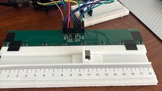
The primary is made with 25 turns of 30-gauge magnet wire with a center diameter of 1 inch. Because engineers are incapable of throwing anything away, I used an empty hookup wire spool with one end cut off to slide off the magnet wire.
To keep the coil from unwinding, you can cut off a small piece of extra magnet wire and wrap it around the primary on two of the sides so that it will hold its shape. The enamel coating on the wire makes it hard for solder to stick to the wire. So, with a little bit of sandpaper, file off some of the enamel so that you can solder on a couple of pins as shown below, or solder wire directly to the coil to reach the breadboard.
Making The Secondary
The secondary side was made in the same way, except using 100 turns of magnet wire this time, along with a diode and two capacitors to convert the AC power to DC power for the LED. Refer to the schematic below.
Schematic for Creating the Wireless Power Transfer Secondary
Cut off some extra pieces of magnet wire to hold the secondary together as was done with the primary. Cut off larger pieces this time to loop around the heatsink of the LED to hold in the center of the secondary. A piece of double-sided tape was used to hold the magnets to the bottom of the LED heatsink. Make sure when positioning the magnets that the mark on the magnets is facing away from the LED.
Assembled Secondary - Top
Assembled Secondary - Bottom
Building the Primary Driver and Testing
In order to induce a current across the secondary coil, we need to generate an AC signal using a function or frequency generator that will allow us to find the best frequency to use with these inductors we made. Just like with the op-amp for the levitation circuitry, the function generator cannot source very much current, so we'll need to use another mosfet to drive our primary coil. The circuit is pretty simple, with the square wave input signal having an amplitude of 5V, and a DC offset of 2.5V (what we want is a square wave which goes high to 5V and low to 0V). Make sure to attach a heatsink to this mosfet, as they get pretty hot, pretty quickly.
To find the best frequency to use, I used my LCR meter, which can measure the inductance of my secondary coil, along with getting an accurate value for the C1 from the schematic and calculated the resonant frequency to be around 80kHz. There's a balance between the frequency and current draw from the power supply. The lower the frequency, the brighter the LED will be, but the efficiency is extremely low and the mosfet driving the primary coil will get extremely hot. The best approach to this problem is to determine how high of a frequency can you use and still have sufficient LED brightness.
Attaching the Primary to the Levitating Inductor
Now that the wireless power transfer is working, it's time to attach the wireless power primary inductor to the levitation inductor. With a little bit of electrical tape, attach the 25-turn inductor we made on the bottom of levitation inductor where the hall effect sensor is.
Finding the New Levitation Distance
The weight of the light and magnets is now significantly heavier than with the magnets alone. With the wireless power primary disconnected from the rest of the circuit, use the reference voltage potentiometer to adjust the levitation distance. Because of the mass, the magnets will need to be significantly closer, around 1cm. Turning the voltage down on the potentiometer will decrease the levitation distance. Once you have the light levitating, you can reconnect the primary and turn the output of the function generator on and off to control the LED.
I mentioned earlier that this was inefficient. Just how inefficient though? I measured the current to be around 50mA, and the voltage across the LED was 2.72V, so the circuit is receiving around 136mW of power. The power supply is set to 12V, and with the magnet levitating and the light on, the circuit is drawing 886mA, or 10.6 watts, which makes the efficiency 1.3%. To be fair though, the levitation circuit is drawing about 450mA, so the wireless power transfer efficiency is really about 2.5%. Now that we know what frequency our wireless power circuit can run at, the function generator could be replaced with a new circuit using a 555 timer to generate the square wave signal.
Resources and Going Further
One of the ways you can take this project further is increase the efficiency of the wireless power transfer. If you have access to an LCR meter, which can measure inductance, capacitance, as well as resistance, you can find the exact values of L1 and C1 of the secondary windings and feed the values into a LC resonance calculator. Once you know the resonant frequency of the secondary, you can measure the inductance of the primary coil and have the calculator return the capacitance value. Adding that capacitor in parallel with the primary inductor and adjusting the signal generator to that frequency should increase the efficiency. But for now, checkout some the links below: