Mfr Part # 5395
ADAFRUIT QT PY ESP32 PICO - WIFI
Adafruit Industries LLC
License: None LED Strips Proximity Wifi
Guide by Erin St Blaine and Tyeth Gundry
Step up your decor game this year with a motion-sensitive fog machine. This guide will show you how to hack a standard-issue Halloween-store fog machine to add lights and reactivity, and also how to use Adafruit IO to control your lights and fog from your smart phone -- from anywhere in the world!
Make your yard dragon breathe its fiery foggy breath whenever trick-or-treaters happen by. This project will level up your Haunted House with jump-scare fun and gorgeous thick, luscious fog.
This project is for intermediate/advanced makers. It has some fairly tricky soldering work using a perma-proto breadboard and a few tiny wires that require a confident touch. There are a lot of pieces to account for, so give yourself some time to sort it all out.
The good news is, the coding is fairly easy using Adafruit IO and Wippersnapper. Use the handy dropdown menus or blockly blocks to design and customize your user experience.
We're using a standard-issue fog machine from Amazon. There are a lot of different ones available so shop around. Be sure you're getting one that uses the remote and control box pictured here.
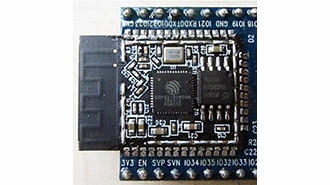
The QT Py Pico is a workhorse of a board at an inexpensive price. It's one of my favorites. ESP32 technology works seamlessly over WiFi to enable all kinds of IoT shenanigans.
This little board will replace the 12v battery inside the fog machine's RF remote so your effects will last all night long.
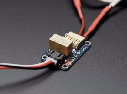
The relays are what make the magic happen for this project. A relay is like an automatic switch. It lets a small electrical signal turn on or off something bigger, like a light or motor, without the two being directly connected. Think of it like using a remote to open a garage door—the small button press (the low-power signal) triggers the big motor (the high-power part) to lift the door.
We'll be using the relays to "press" the buttons on the fog machine's RF remote control. You'll need two of them for this project.
The PIR sensor is the trigger. Place it where people will walk by to start your lights and fog.
You'll also want some pixels for the light effect. Choose the right type for your project. I like the 60/m tape because it's versatile and flexible, but sometimes you want high-density pixels or one of our NeoPixel rings or jewels. Shop around, Adafruit hast so many fun form factors.
2 x Stemma Connector
4 x Thin 30awg Wire
1 x Solid Core Wire
1 x USB C Cable
I also used:
Alien Tape (spoooky!)
A fog hose extension kit from Home Depot
Black duct tape
Soldering iron & accessories
Hot glue gun
Tiny screwdriver
Dremel
QT Py Wiring
+5v to 5v power rail (red)
G to G power rail (blue)
PIR Sensor Wiring
+5v to 5v power rail (red)
G to G power rail (blue)
Data to A0
Relay Wiring
Red wire to 5v power rail (red)
Black wire to G power rail (blue)
White wire to A1 & A2
RF Remote Wiring
Start button to NO and COM on Relay 1
Stop button to COM and NO on Relay 2
12V Bias Voltage Booster Wiring
IN to 5v power rail (red)
G to G power rail (blue)
G to RF remote - battery terminal
12v to RF remote + battery terminal
NeoPixel Wiring
+5v to 5v power rail (red)
G to G power rail (blue)
Data IN to A3
The WipperSnapper firmware and ecosystem are in BETA and are actively being developed to add functionality, more boards, more sensors, and fix bugs. We encourage you to try out WipperSnapper with the understanding that it is not final release software and is still in development. If you encounter any bugs, glitches, or difficulties during the beta period, or with this guide, please contact us via http://io.adafruit.com/support
WipperSnapper is a firmware designed to turn any WiFi-capable board into an Internet-of-Things device without programming a single line of code. WipperSnapper connects to Adafruit IO, a web platform designed (by Adafruit!) to display, respond, and interact with your project's data.
Simply load the WipperSnapper firmware onto your board, add credentials, and plug it into power. Your board will automatically register itself with your Adafruit IO account.
From there, you can add components to your board such as buttons, switches, potentiometers, sensors, and more! Components are dynamically added to hardware, so you can immediately start interacting, logging, and streaming the data your projects produce without writing code.
You will need an Adafruit IO account to use WipperSnapper on your board. If you do not already have one, head over to io.adafruit.com to create a free account.
Many ESP32 boards have a USB-to-Serial converter that talks to the chip itself and will need a driver on your computer's operating system. The driver is available for Mac, Windows, and Linux.
Click here to download the CP2104/CP2102N driver
Newer ESP32 boards have a different USB-to-serial converter that talks to the chip itself and will need a driver on your computer's operating system. The driver is available for Mac and Windows. It is already built into Linux.
If you would like more detail, check out the guide on installing these drivers.
Click here to download the Windows driver
Click here to download the Mac driver
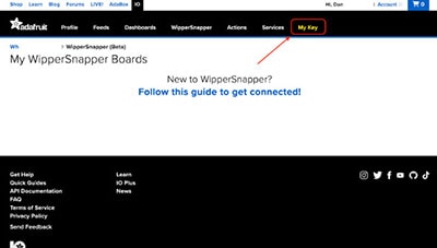
Log into your Adafruit IO account. Click the New Device button at the top of the page.
After clicking New Device, you should be on the board selector page. This page displays every board that is compatible with the WipperSnapper firmware.
In the board selector page's search bar, search for the QT Py ESP32 Pico. Once you've located the board, you'd like to install WipperSnapper on, click the Choose Board button to bring you to the self-guided installation wizard.
Follow the step-by-step instructions on the page to install WipperSnapper on your device and connect it to Adafruit IO.
If the installation was successful, a popover should appear displaying that your board has successfully been detected by Adafruit IO.
Give your board a name and click "Continue to Device Page".
You should be brought to your board's device page.
Adafruit.io WipperSnapper is in beta, and you can help improve it!
If you have suggestions or general feedback about the installation process - visit https://io.adafruit.com/support, click "Contact Adafruit IO Support" and select "I have feedback or suggestions for the WipperSnapper Beta".
If you encountered an issue during installation, please try the steps below first.
If you're still unable to resolve the issue, or if your issue is not listed below, get in touch with us directly at https://io.adafruit.com/support. Make sure to click "Contact Adafruit IO Support" and select "There is an issue with WipperSnapper. Something is broken!"
I don't see my board on Adafruit IO, it is stuck connecting to WiFi
First, make sure that you selected the correct board on the board selector.
Next, please make sure that you entered your WiFi credentials properly, there are no spaces/special characters in either your network name (SSID) or password, and that you are connected to a 2.4GHz wireless network.
If you're still unable to connect your board to WiFi, please make a new post on the WipperSnapper technical support forum with the error you're experiencing, the LED colors which are blinking, and the board you're using.
I don't see my board on Adafruit IO, it is stuck "Registering with Adafruit IO"
Try hard resetting your board by unplugging it from USB power and plugging it back in.
If the error is still occurring, please make a new post on the WipperSnapper technical support forum with information about what you're experiencing, the LED colors which are blinking (if applicable), and the board you're using.
WipperSnapper firmware is an application that is loaded onto your board. There is nothing to "uninstall". However, you may want to "move" your board from running WipperSnapper to running Arduino or CircuitPython. You also may need to restore your board to the state it was shipped to you from the Adafruit factory.
Follow the steps on the Installing CircuitPython page to install CircuitPython on your board running WipperSnapper.
If you are unable to double-tap the RST button to enter the UF2 bootloader, follow the "Factory Resetting a WipperSnapper Board" instructions below.
Uploading this sketch will overwrite WipperSnapper. If you want to re-install WipperSnapper, follow the instructions at the top of this page.
If you want to use your board with Arduino, you will use the Arduino IDE to load any sketch onto your board.
First, follow the page below to set up your Arduino IDE environment for use with your board.
Then, follow the page below to upload the "Arduino Blink" sketch to your board.
Uploading this sketch will overwrite WipperSnapper. If you want to re-install WipperSnapper, follow the instructions at the top of this page.
Sometimes, hardware gets into a state that requires it to be "restored" to the original state it shipped in. If you'd like to get your board back to its original factory state, follow the guide below.
Factory Reset Adafruit QT Py ESP32 Pico
There are a lot of pieces to this project. I started out using a solderless breadboard and jumper wires / alligator clips to get everything in place and make sure it all worked. These boards are meant for prototyping and can make the wire spaghetti mess a lot easier to sort out.
When I was happy with the setup and placement of components, I transferred everything to a perma-proto breadboard and soldered it in place.
Solder headers onto your QT Py and attach it to your breadboard. Connect the G pin to the G (blue) power rail and the 5v pin to the red power rail.
We'll be attaching all the G and 5v wires from our components to the power rails we've just created. This is much easier than trying to solder EVERY G wire to that one pin on the QT Py.
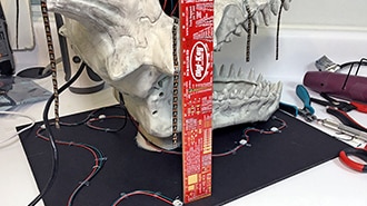
The RF remote has two buttons inside: one for starting the smoke and one for stopping it. We need a relay for each button to actuate it using Adafruit IO.
Open up the RF remote by removing the tiny screw on the back. Take the battery out -- you never want to solder to a live circuit. You'll see two momentary switch buttons inside. Carefully and gently solder a tiny wire to each leg of each button. Connect them to your two relays as shown.
Make your wires a little longer than pictured here -- I had to go in and lengthen these a bit to give myself room in the enclosure.
Our Adafruit IO controls use the relays to "hold" these buttons down for a while. The remote wasn't really designed with this in mind, and the little 12v battery in there wears out really fast. When that battery dies, the smoke can't be stopped and the dragon gets out of control quickly. Luckily we have a solution to keep our villagers safe from excessive dragon smoke: we can power the remote using a 12v power boost and bypass the battery altogether.
Solder a red wire to the positive battery terminal on your remote, and a black wire to the negative (the one with the spring). We'll connect the other end of these wires to our 12v booster board.
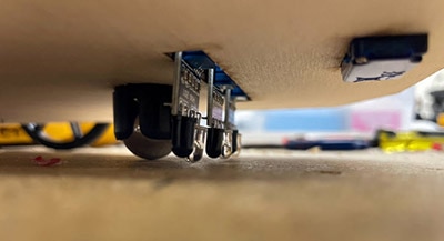
Flip the board over and attach the relays to the back of the breadboard using thick mounting tape. Solder the connectors to the breadboard as shown: red wires to the red power rail, black wires to the blue power rail. The white wires will connect to pins A1 & A2.
Solder the 12v booster in between the relays. Connect G to the blue power rail and IN to the red power rail.
Connect the red wire from your remote battery terminal to 12v, and the black wire to the G power rail.
The PIR sensor will need protection from the elements. I found a little plastic box that fits the sensor and closes tightly, and cut a hole in the top with my Dremel that's just the right size for the Fresnel lens to poke through.
I sealed the sensor in place with some hot glue, then cut the female connector off and physically soldered the 3 wires to the pins. This gave me a little bit of a lower profile so the sensor fit in the box better and also gives me more assurance that the wires will stay in place.
Connect the 3 wires from the PIR sensor to the breadboard: red to the red power rail, black to the blue power rail, and yellow to pin A0.
The NeoPixels will need to be installed in the dragon, which isn't going to be easy. I used a JST connector on the strand so I can put the pixels in place and leave them there while I futz around with the rest of the electronics. I sealed them up really well so they should be waterproof enough to last through the rainy season without having to be removed. I don't want to leave my electronics case out there though, so using a connector is a great way to keep this project working year after year without having to completely disassemble everything.
Solder a male 3-pin JST connector for the NeoPixel strand as shown: red to the red power rail, G (white wire in this case) to the blue power rail and the middle wire (Data IN) will go to pin A3.
Caution: the color coding on these connectors varies greatly. It doesn't matter which color goes where as long as the wires match up correctly with your NeoPixel strip. It helps to plug in the female side of the connector before soldering to the strip, so you can get a physical look at which wire is going where.
Solder the other side of the JST connector to your NeoPixel strip. Remember to give yourself enough lead wire on the connectors that the pixels and electronics don't have to be all in the same spot.
I cut a few holes in the sides of my plastic enclosure box so the wires can come out, then stuck the remote to the top with some alien tape. I like keeping the remote outside the box so the buttons can be accessed manually, in case it's needed.
Plug a USB cable into your QT Py. If you've already installed WipperSnapper, you should see a blinking yellow light for a few seconds and then a blinking blue light. This means your board is connecting to WiFi and is ready to make some magic happen.
You should also see power to the RF remote. Press the buttons and be sure a little red light comes on, or turn on your fog machine to be sure the buttons are doing their job.
If that all appears to be working, let's head to Adafruit IO to make our setup Do Stuff!
There are a lot of components and connections happening here. Here are a couple things that might be getting in your way:
If your board isn't giving you yellow and then blue lights, try reinstalling WipperSnapper. Make sure your WiFi credentials are correct and that you are within range of the WiFi network.
If your remote isn't coming on, be sure you've got the red and black wires from the 12v booster going to the correct battery terminals. The black wire goes to the one with the spring.
If the remote just won't make the fog happen, remember that the fog machine needs to warm up for a few seconds to a full minute before it's ready to go. There is a red light on the wired controller box that appears when the fog is ready. Wait until that light comes on and then try the remote again.
Carefully check your breadboard under a magnifier to make sure you don't have any short circuits / solder bridges, especially between the red and black power rails. We used those things a lot, and it's easy to miss a little misplaced blob of solder, which can wreck your whole day. If you try to power it up and don't get power, this is definitely something to check.
Now it's time to dive into controlling your project with Adafruit IO. There are some excellent starter guides available to give you an overview of how it all works. To get a basic understanding start with the Welcome to Adafruit IO guide and then check out this guide on Dashboards and Scheduling Actions.
The interface is pretty self-explanatory and easy to use once you're familiar with the concepts.
First, we'll set up our components.
We've got 4 different components:
PIR Sensor: Connected to pin A0
Relay -- this one is connected to the "start" smoke button on pin A1
Relay 2 -- this is connected to the "stop" smoke button on pin A2
NeoPixel strip: connected to pin A3
Click "Add Component" to find each component type and add it with its corresponding pin number.
You'll also have an opportunity to set your number of pixels in the NeoPixel setup.
Now that the Components are set up, it's time to make them do stuff using Actions.
Each Action will tell the QT Py to perform one function. There is a lot you can do with Actions, mostly things like:
Turn your relay on
Turn your relay off
Read data from the PIR (passive infrared sensor)
Turn your NeoPixel color LED strip on in a specific color
To plan out Actions, break down exactly what you want the project to do.
When the PIR sensor gets triggered, turn on the relay (start button)
When the PIR sensor gets triggered, turn on the NeoPixels in red
When the PIR sensor resets, turn off the relay and turn on relay 2 (stop button)
When the PIR sensor resets, turn off the NeoPixels
After 10 seconds, turn off relay 2
This covers my basic actions.
Adafruit IO has two different kinds of triggers for actions. We can pick from various trigger blocks that react to incoming data:
if (component) is in a certain state, then do (x).
Or Schedule blocks, where something happens at a specific time of day, so you can turn your project off when it's time for trick-or-treaters to go to bed.
It's possible to use multiple trigger blocks, and when any of them are triggered then the action will fire, although repeated executions are subject to a cooldown period (currently 5 seconds).
Lastly, there is a Settings option for the Root action block which allows delaying the execution of the action for a specified amount of time after receiving a trigger condition:
if (component) is in a certain state, then do (x) after a set amount of time
Start by visiting the Actions page, using the link in the navigation menu bar.
Here all of your actions are displayed, showing names and descriptions along with the enabled state (Off/On toggle button), and the information icon at the end of each row.
Click "Create Action" and enter a suitable name and optional description. Make it obvious what the action does.
Now you'll be presented with the Actions workspace, with one Root block in the diagram, and a toolbox full of blocks to craft your action.
Start with the Triggers category, and drag the block labelled When feed gets data matching = 0 onto the Triggers: section of the root block. It will snap into place when the notches line up.
Select the PIR component from the Feed dropdown in the newly placed block.
Change the value in the block from zero to one (1). This checks the state: enter 1 for on, or 0 for off for the relays and sensors.
Now from the Feeds category in the toolbox, drag a Set Feed block into the Actions: section of the root block.
Select the your target component from the feed dropdown in the placed block.
This will set the component state to whatever value you enter. Again, enter 1 for on, or 0 for off for the relays.
Now you can use the Save button and Enable the action if asked.
For the NeoPixel strip, things work much the same, only instead of using a 1 or a 0 in the "with" box, put a hex code indicating the color you'd like to see. I wanted red, so I entered #FF0000.
To turn the pixels back off, use a hex code of black: #000000
These relays and switches are also not 100% reliable -- they sometimes get a little confused and don't turn off. After some testing and playing around, I ended up adding a few more actions as a failsafe, turning the relays and lights to "off" after a set amount of time with no triggers, so that the smoke or lights never get stuck in an "on" state.
Using the delay setting option for the Action, accessed with the Grey Cog in a Blue Background button, it's possible to set the action to run after a 3-4 second delay.
Creating an action to turn off the smoke relay, based on the relay receiving an On trigger first, but with a 3 second delay should act as a fail-safe.
Our PIR sensor can also help us out here. It has two screws on the side. One of them controls the sensor's sensitivity, and the other controls the amount of time that elapses before the sensor resets after it's been triggered. By creating Reactive actions based on the reset time of the PIR sensor (i.e. When the PIR sensor's state resets to 0, do "x") we get a little more control over the trigger time. Just turn your screw to adjust.
Here is my final setup, with fail-safe actions included.
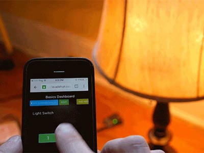
One of the coolest things about Adafruit IO is that you can control your project from anywhere in the world over the internet using your smart phone or any web-enabled browser.
This page will show you how to create a dashboard with handy switches so you can start or stop the dragon smoke or turn on the NeoPixels from anywhere in the world with an internet connection.
Head to the Dashboards tab and click "Create a New Dashboard". Give it a name and description and an image if you like.
Open the edit menu on the upper right and select "Create New Block". You'll get a menu showing all the different block types. Select the second one: Momentary Button.
Connect your button to Relay (the one that controls the "start" button on your remote).
On the next screen you can give it a name and customize the behavior. I called mine "Start Smoke".
Create a second button connected to Relay 2 and call it "Stop Smoke". The rest of the settings are the same. I made mine red.
You can also create a block for controlling the NeoPixel strip. Choose the "Color Picker" block and assign it to the NeoPixel component.
Head over to Adafruit IO with your phone and log in. Choose your device and head to the Dragon dashboard. You've now got a custom remote control where you can start and stop the smoke and change the pixel colors at will!
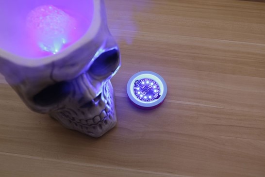
My yard dragon is holding a little metal orb, which is just perfect for hiding some sensors and electronics. Find a spot on your project where you can hide the PIR sensor at kid-motion level.
I secured it in place with some packing tape.. not a permanent solution, but it'll hold through Halloween.
I got a 10' USB C cable from Amazon and ran it through the back of the orb and out the bottom of the dragon, so the electronics and the fog machine can be powered from the same extension cord.
I sealed up the ends of my NeoPixel strip using hot glue and clear heat shrink. Then I threaded the strand down through the mouth and into the belly of the dragon, where I was able to grab the JST connector and thread it in through the back of the orb, where it can plug into my electronics enclosure.
To get the smoke where I wanted it, I bought a Fog Tube Accessory Kit from Home Depot. This came with a long tube that had holes cut all along its length, and a screw-on adapter for the front of the machine.
I cut the tube to the right length and taped up all the holes with gaffer's tape. I want the smoke to come only out of the end.
I dropped the fog tube down the back of the dragon's throat, alongside the NeoPixel strip. I ended up taping the two together to keep them in place. The tube comes out the bottom of the dragon where it attaches to the fog machine.
Extra smoke spilled out through the dragon's eyes and a hole in the top of her head, so I covered the holes from the inside with clear packing tape. Now the smoke just comes out her mouth and nose.
The PIR sensor has a couple adjustment screws on the side, one of which changes sensor sensitivity and the other which adjusts the amount of time between trigger and reset. Play with the settings until your project is all dialed in.
Halloween store fog juice is easy to find at a certain time of year, but we can get much thicker and more dramatic smoke by making our own fog juice.
The ingredients are Glycerin and Propylene Glycol, mixed 50/50 or to your liking. Add a little water if you'd like to thin it out.
If you get a little heavy-handed with the glycerin, it may clog your machine. If this happens, run some vinegar through the machine until the clogs clear out. In fact, it's a good idea to do this whenever you put the fog machine away for storage or after a night of heavy use.