Use Digital Predistortion to Create a Near-Perfect Precision Signal Generator
It’s always been a challenge to create high-precision standard waveforms, such as sine and arbitrary waveforms using all-analog circuitry, as numerous subtle and unavoidable sources of error must be identified and overcome. Incorporating digital predistortion (DPD) into the design and combining it with output-driven feedback significantly improves achievable performance.
Precision is a frequently cited and required system and performance designation. In test and measurement, it can refer to absolute accuracy, superior consistency, high linearity, high resolution, overall waveform purity, low distortion, and minimization of noise and artifacts.
Designers may employ a mix of strategies to achieve their needed precision. Such strategies include:
- Choosing components with higher accuracy and lower temperature-drift coefficients, even aging them before use to drive out imperfections and drift tendencies. This is often done with voltage references where a single high-accuracy, low-drift part can greatly benefit system performance.
- Using circuit topologies offering self-cancellation of error sources, such as ratiometric arrangements. This may mean using the classic Wheatstone bridge or a differential amplifier with paired resistors on a common substrate with the benefit of matched temperature-related drift.
- Implementing compensation schemes where components with equal but opposite temperature drifts are used together to cancel out the changes.
- Adhering to best practices for physical layout, including large ground planes, management of current flows, avoiding local thermal differentials, and identifying and eliminating inadvertent thermocouples due to mismatches between materials such as copper printed circuit board (pc board) tracks and tin-plated component leads.
- Using a one-time calibration of the system against a known standard, then tweaking the circuitry using analog components such as trimpots or, more commonly, digitally stored correction factors.
DPD, a more sophisticated approach, is often used by designers of high-speed data links. Rather than attempting to improve the link channel, which is usually impractical or impossible to control, this technique characterizes the channel distortion. It then creates a bit waveform with an inverse distortion waveshape so that this predistorted waveform and the channel distortion cancel each other out. This reduces the bit error rate (BER) and supports higher data rates. In the most advanced implementations, the predistortion settings are not static but are dynamically adjusted in real-time to adapt as channel conditions change.
Predistortion provides precision for analog waveforms
DPD is useful for more than just high-speed digital signals. It can also be used to improve an analog function generator’s waveforms. This capability is demonstrated by Analog Devices’ ADMX1002B (Figure 1) ultra-low distortion, low-noise, digitally controlled arbitrary waveform generator (AWG). Note that the otherwise identical ADMX1001B version adds a differential analog-input signal-acquisition channel; more on this version later. The EVAL-ADMX100X-FMCZ evaluation kit supports both.
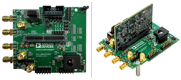 Figure 1: The ADMX1002B (left) is a high-precision sine and arbitrary waveform generator; the ADMX1001B (right) is similar but adds a data-acquisition channel in the form of a board that is inserted into a connector on the ADMX1002B. (Image source: Analog Devices)
The ADMX1002B provides the highest-purity differential sinusoidal signals in its class by exploiting a DPD algorithm, using a patented method for sensing and correcting its output (Figure 2).
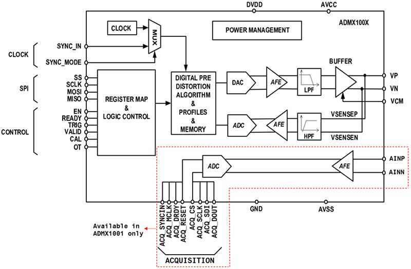 Figure 2: The ADMX1002B incorporates a DPD algorithm and senses and corrects its own output for the highest precision; the ADMX1001B adds the data-acquisition circuitry shown at the bottom and lower right of the block diagram. (Image source: Analog Devices)
The unit provides outputs from 30 Hertz (Hz) to 40 kilohertz (kHz) when not using the DPD algorithm, and up to 20 kHz with DPD invoked. The supplied PC-based graphical user interface (GUI) connects to a System Demonstration Platform (SDP) controller board via a USB connection.
Non-DPD is the default mode when a new sine-wave frequency or amplitude is loaded into the register; this is the initial operating mode for arbitrary waveform generation. Due to its architecture, the ADMX1002 module’s performance exceeds the native performance of the components, even in non-DPD mode.
Software or hardware can enable the DPD algorithm. The process requires no external reference inputs and exploits a patented differential temporal and amplitude sensing method.
The algorithm requires that the sense inputs be connected to the output of the ADMX1001 to be used in the processor routine to generate an ultra-high purity sine waveform. With DPD enabled, total harmonic distortion (THD) at 1 kHz is an extremely low typical value of -130 decibels (dB) (amplitude up to 3.62 volts rms) and only degrades by a few decibels all the way to 20 kHz (Figure 3).
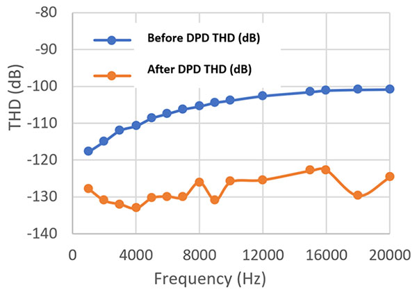 Figure 3: A graph of frequency versus THD clearly shows the improvement in THD with added DPD. (Image source: Analog Devices)
DPD also greatly enhances sine waveform purity, as shown by the fast Fourier transform (FFT) at 1 kHz with 2 volts rms output before and after DPD (Figure 4).
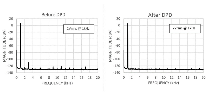 Figure 4: Invoking DPD greatly enhances sinewave purity by attenuating odd and even harmonics of the fundamental frequency, as seen by measurements taken before (left) and after (right) DPD. (Image source: Analog Devices)
Going beyond the single sine-wave output
The ADMX1002B can also generate two-tone sine waves from 30 Hz to 20 kHz in burst or continuous mode. The waveform frequencies can be programmed with a high precision of 1 microhertz (µHz) resolution, and the amplitudes can be programmed with 1 microvolt (µV) resolution./p>
Further, the unit can function as a user-programmed AWG. The AWG signal can be programmed to be up to 20 seconds (s) long and stored in volatile memory. Continuous AWG generation can be implemented by looping back the stored waveform. The ADMX1002's output contains a 27 kHz low-pass filter, allowing AWG waveforms to be generated within this band.
DC outputs are also available. The ADMX1002 can generate differential DC output signals up to 11.3 volts DC (VDC) between the positive and negative output connections Vp and Vn. This output level can be adjusted in precise steps of 1 µV.
Accepting analog inputs
As noted earlier, Analog Devices also offers the ADMX1001, a superset of the ADMX1002 that has all the functions, features, and performance of the latter, but adds analog input capabilities. This highly integrated data acquisition solution provides seven programmable gain settings with a maximum differential input range of ±7.5 volts and a maximum input common-mode range of ±7 volts. The integral 4th order anti-aliasing filter provides rejection up to −130 dB, while the total dynamic range of the acquisition channel is up to 128 dB with a −115 dB THD (typical) when measured with a 1 kHz input tone at full scale.
Conclusion
DPD provides benefits in the precision generation of analog signals such as single and two-tone sine waves, as well as user-defined arbitrary waveforms. The resulting waveform, measured by standard parameters such as THD and FFTs, shows performance in the 130 dB range over the audio band. The addition of the data-acquisition function in the ADMX1001 adds design versatility.
Related Content
“User Guide for ADMX1001 and ADMX1002, Ultra-low Distortion, Low Noise Signal Generator and Acquisition Evaluation Modules”
https://wiki.analog.com/resources/eval/user-guides/admx/admx100x
“ADMX1001/ADMX1002 Ultralow Distortion Sine Wave and High-Resolution Arbitrary Waveform Generator + Acquisition Module” (video)
https://www.analog.com/en/resources/media-center/videos/6355673963112.html
“High Performance Source for ADC and Audio Test with Novel Digital Predistortion”
https://www.analog.com/en/resources/technical-articles/high-performance-source-for-adc.html

Have questions or comments? Continue the conversation on TechForum, DigiKey's online community and technical resource.
Visit TechForum


