Integrated Time-to-Digital Converters Simplify Time-of-Flight Range-Finding Designs
Time-to-digital converters (TDCs) are electronic devices that precisely measure the time between a start pulse and one or more stop pulses. They greatly simplify time-of-flight (ToF) measurements in a wide variety of applications by integrating all the necessary functions of what is essentially an electronic stopwatch. These functions are fundamental to ranging.
For example, in an ultrasonic range finder, the time between a transmitted ultrasonic pulse and its received echo from a target (Figure 1) is proportional to the distance between the transmitter and the target.
 Figure 1: An ultrasonic range finder measures the time between a transmitted burst (left) and a target's reflection (right) to determine the distance between them. (Image source: Art Pini)
A transmitted pulse propagates to the target, is reflected, and is sensed by the transducer on its return. In this example, the round trip takes 3.5 milliseconds (ms), so the ultrasonic pulse is 1.75 ms from the target. At 22°C, the speed of sound is 344 meters per second (m/s), so the distance is 0.00175 x 344 = 0.6 m.
Similar applications that use ranging, such as radar, light detection and ranging (LiDAR), and sonar, also use ToF between a transmitted pulse and a reflected echo to determine the distance to a target. This is becoming more common in the automotive industry as ranging devices proliferate. ToF calculations are also required in flow rate measurements taken between transducers in upstream and downstream directions to determine fluid velocity
Simplifying the TDC function
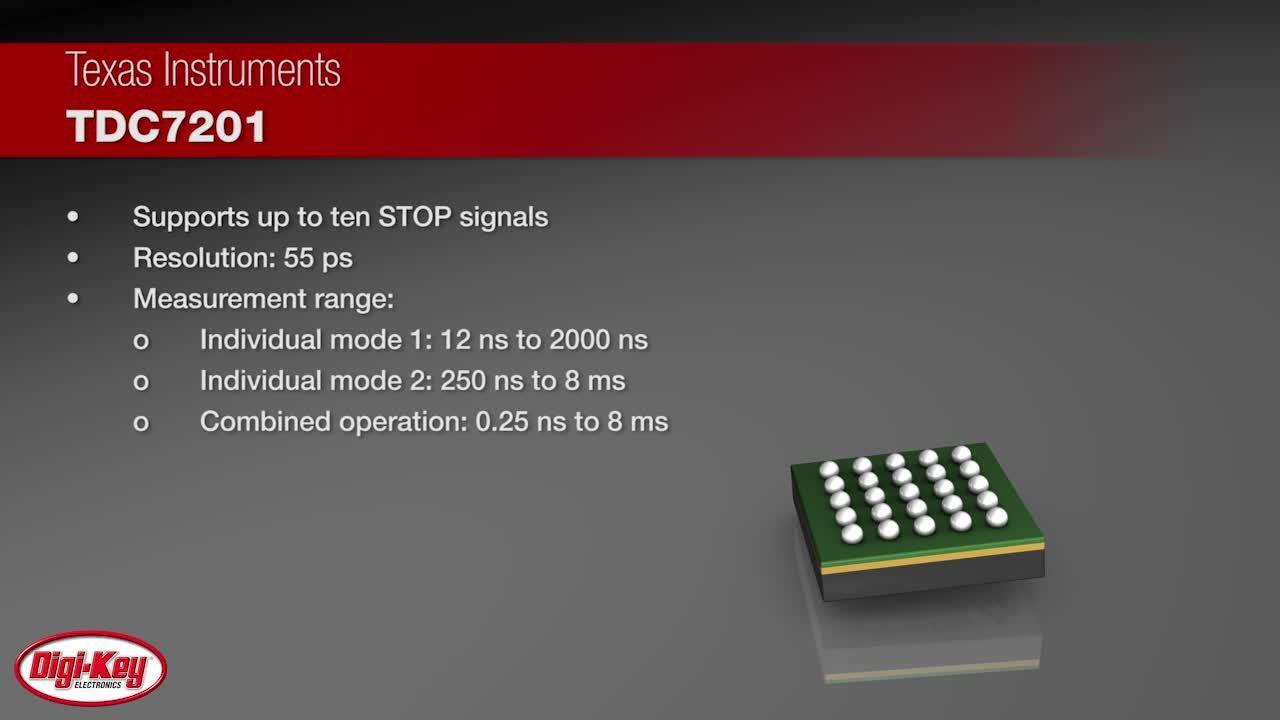
Designers aim to simplify the TDC function as much as possible to save time and space. To help with this, highly integrated TDCs have become available. For example, the Texas Instruments’ TDC7201ZAXR (Figure 2) is a dual TDC integrated circuit (IC) intended for range finding in automotive applications such as advanced driver assistance systems (ADAS) using ToF techniques. The TDC7201ZAXR features two measurement modes: mode 1 covers 12 to 2000 nanoseconds (ns), while mode 2 ranges from 250 ns to 8 milliseconds (ms). Time resolution in either mode is 55 picoseconds (ps). This TDC uses an externally supplied clock, an internal ring oscillator, and the respective counters to measure ToF between a common start pulse and up to six stop pulses.
 Figure 2: The functional block diagram of the TDC7201ZAXR shows the dual TDC cores using independent ring oscillators, coarse counters, external clocks, and clock counters. (Image source: Texas Instruments)
The TDC7201ZAXR is powered by a 2 to 3.6 volt DC (VDC) source. Internally, a low dropout regulator provides a stable power source for the TDC timebase. Schmitt-triggered comparators condition and shape the input start and stop signals. The ring oscillator in each TDC is each TDC core's primary time measurement mechanism. The coarse counter is associated with the ring oscillator, while the external clock drives the clock counter. The external clock needs to be a frequency-stable source, as the timing accuracy of the TDC directly depends on the clock accuracy. The external clock is a reference for calibrating the internal ring oscillator-based timebase. The recommended clock frequency ranges from 8 to 16 megahertz (MHz) for optimum timing accuracy.
Examining the TDC operating modes helps us understand how it works. Mode 1, for a timing range less than 2000 ns, uses the ring oscillator output and the coarse counter (Figure 3).
 Figure 3: Mode 1 uses the ring oscillator exclusively to drive the coarse counter, yielding 55 ps timing resolution for ToFs less than 2000 ns. (Image source: Texas Instruments)
The ring oscillator period sets the timing resolution, nominally 55 ps, determined precisely by the internal calibration against the external clock. The ToFs between the start pulse and up to six stop pulses are stored to specific register locations.
Mode 2 increases the time range to 8 ms while maintaining the same nominal 55 ps time resolution (Figure 4).
 Figure 4: Mode 2 utilizes the clock counter, counting external clock periods, and the coarse counter, counting ring oscillator periods between the start pulse and the following external clock, and between the stop pulse and the following external clock. (Image source: Texas Instruments)
The coarse counter serves as a vernier, measuring the time between the start pulse and the next external clock edge. It also measures the time between the stop pulses and the following external clock edges. This combination yields a time resolution of the coarse counter while extending the measurement range.
The TDC7201ZAXR is controlled using a serial peripheral interface (SPI), which differentiates between the two TDCs using the chip select line. Measured time outputs and device configuration are accomplished using the SPI interface.
If you want to try this TDC, start with the TDC7201-ZAX-EVM evaluation board. This board allows you to evaluate the operation and performance of the TDC7201 and has an easy-to-use graphical user interface (GUI).
The Analog Devices’ MAX35101EHJ+ is a TDC for heat meter and flowmeter applications. It features a time resolution of 20 ps and a maximum range of 8 ms. It also features a complete analog front-end (AFE) in the form of an amplifier and a comparator. In addition, it provides high-accuracy temperature measurements, an 8 kilobyte (Kbyte) non-volatile memory for data logging, and a real-time clock.
A heat meter measures thermal energy by determining the fluid velocity in a hot water heating system using ToF measurements in both the upstream and downstream directions (Figure 5).
 Figure 5: A heat meter based on ToF measurement determines water velocity through the spool body using upstream and downstream piezo-electric transducers. (Image source: Analog Devices)
A heat meter measures the heat energy delivered through a radiator. Using a resistance temperature detector (RTD), it measures the inlet and outlet temperatures. The spool body ensures that water flows through an opening with a known diameter. The spool body contains piezo-electric transducers that the MAX35101EHJ+ pulses in upstream and downstream directions. The difference in the ToF measurements provides the water flow velocity. That information, combined with the known opening area, can be used to determine the flow volume. Combining this with the temperature drop, the amount of heat energy dissipated by the radiator can be calculated. The MAX35101EHJ+ is self-contained and performs all the required measurements.
Conclusion
The TDC is a critical element that enables many ToF measurements in automotive, industrial, and research applications. Highly integrated and capable devices are available from Texas Instruments and Analog Devices to simplify the design process. Eval boards are also available to ensure the devices meet your application criteria.
About this author

Arthur (Art) Pini is a contributing author at DigiKey. He has a Bachelor of Electrical Engineering degree from City College of New York and a Master of Electrical Engineering degree from the City University of New York. He has over 50 years experience in electronics and has worked in key engineering and marketing roles at Teledyne LeCroy, Summation, Wavetek, and Nicolet Scientific. He has interests in measurement technology and extensive experience with oscilloscopes, spectrum analyzers, arbitrary waveform generators, digitizers, and power meters.

Have questions or comments? Continue the conversation on TechForum, DigiKey's online community and technical resource.
Visit TechForumMore Blogs from this Author