Get a Grip on the Nuances of High-Voltage Passive Components
While many engineers are focused on low-voltage systems with rails in the single digits, an increasingly visible and vital fraction of design effort is now in the high-voltage world. Of course, higher voltages have always been in use, as they are needed to efficiently supply high-power applications. Now, however, with so much attention being given to electric vehicles (EVs) of various types, renewable energy, and associated energy storage systems—and energy efficiency in general—there’s been an increase in the need for power rails and components operating at hundreds of volts, or higher.
Even though many of these high-voltage designs may look similar to their low-voltage siblings on schematic diagrams, there’s a huge difference between building a rechargeable battery subsystem delivering a few volts and watts versus, for example, the power pack of an EV operating at 600 to 800 volts delivering kilowatts and storing megajoules. Not only must the active components such as MOSFETs be rated for these higher voltages, but the associated passive components—resistors, capacitors, contacts, connectors, and others—must also be suitably rated.
In short: the modest basic guidelines of low-voltage circuits no longer dominate. Instead, it’s an unforgiving world of arcing, sparks, insulation breakdown, contact fretting, and material deterioration. Mistakes in material choices, component selection, and physical placement are costly and often dangerous, while re-designs and re-spins, however minor they seem at first glance, are time-consuming, frustrating, and subject to in-depth design re-review.
The implications of high-voltage design
What does this mean in practice? First, there are many standards that define insulation, isolation, and other requirements for the high-voltage world, and these become increasingly strict and challenging as the voltage goes into the hundreds and even thousands of volts. Some of these standards are promulgated by government-linked regulatory organizations, while others are set by industry associations, and some are defined by good engineering practice.
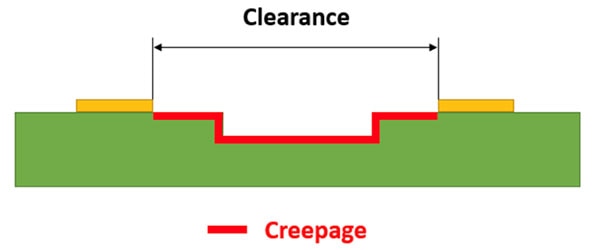
One of the most tangible requirements is related to minimum clearance and creepage. These come into effect when the operating voltage is above 30 volts AC or 60 volts DC, as voltages above these levels are considered potentially hazardous. Clearance is the shortest distance through air between two conductors, while creepage measures the shortest distance along the surface of the insulation material (Figure 1).
 Figure 1: High-voltage layout considerations begin with clearance, the shortest distance through air between two conductors, and creepage, which is the shortest distance along the surface of the insulation material. (Image source: Altium Limited)
The printed circuit board (pc board) layout requirements for minimum clearance and creepage dimensions vary with the materials, voltage, and environmental conditions. The IEC 60601 and IPC 2221 standards are the primary guidelines for spacing between conductors at different voltages and scenarios, but there are many additional ones that are application specific. In addition to those basic requirements, there are standards defining materials such as insulation types and thickness. Here, too, there are subtleties, such as the difference between “UL listed” and “UL recognized” classifications (see Related Content).
Components also differ radically
Even if a design meets all the physical regulatory standards, including creepage and clearance commensurate with the design’s high-voltage classification, there’s much more work to be done to create a suitable bill of materials (BOM). A resistor that will function and survive in service at hundreds of volts is very different when compared to one for the modest and benign 10 to 20 volt region. Every aspect of its design, materials selection, production process, and overall packaging is unique.
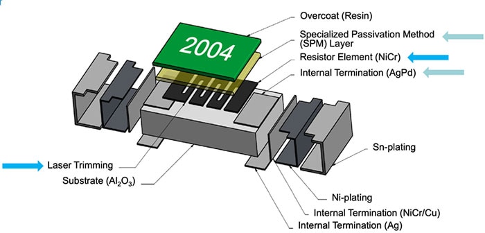
For example, the Vishay Dale TNPV series of automotive qualified (AEC-Q200) thin-film high-voltage resistors, such as the 330 kilo ohm (kΩ) TNPV1206330KBYEA, are designed for operation to 1000 volts. As they are intended primarily for accurate high-voltage measurement, their sophisticated material, construction, and laser trimming yields fairly tight specifications. Among these are a low-voltage coefficient below 1 part per million per volt (ppm/V), tolerance down to ±0.1%, and a temperature coefficient of resistance (TCR) as low as ±10 ppm/⁰C (Figure 2).
 Figure 2: Resistors in the TNPV series use a combination of specialized materials, design, and fabrication to achieve the required high-voltage operation and tolerances. (Image source: Vishay Dale)
Vishay notes that fine trimming helps to reduce voltage gradients along the segments of the resistive element, thus enhancing stability at high voltages. This advanced design and construction ensures application stability and precision in what is otherwise an ordinary-looking chip resistor housed in a standard 3216 (metric) package.
It’s a similar situation with capacitors. Consider the FHC16I0307K, a 300 microfarad (µF) film capacitor from Kyocera AVX’s FHC Series, which protects power semiconductors in electric and hybrid electric vehicles. It does this by providing DC filtering and preventing ripple currents from reaching back to the power source and by smoothing out DC bus voltage variations.
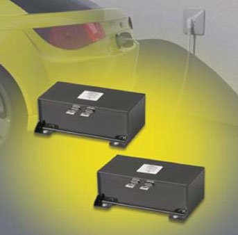
Meeting AEC-Q200 and IEC 61071-1/IEC 61071-2 (for power electronic capacitors), the FHC16I0307K is specially treated to have a very high dielectric strength in operating conditions up to 115°C and is housed in a rectangular, resin-filled metalized plastic case measuring 237 × 72 × 50 millimeters (Figure 3). While low-voltage 300 µF filtering capacitors are very common, these are rated for 450 volts DC operation. They use a dry-wound (non-oil-filled), segmented, metalized polypropylene construction which features a controlled self-healing process.
 Figure 3: The FHC16I0307K bulk capacitors are designed for automotive use. They are rated to 450 volts DC, use metalized polypropylene construction, and are housed in a metalized plastic case. (Image source: Kyocera AVX)
Further, a unique feature of the segmented metalized technology is how the capacitor acts at the end of its lifetime. Unlike electrolytic capacitors—which exhibit a short-circuit failure mode—these film capacitors only experience a parametric loss of capacitance, with no catastrophic failure mode. Instead, the capacitor gradually and gracefully loses capacitance over its lifetime, eventually becoming an open circuit.
Conclusion
While the schematics may look similar to low-voltage circuits, designers involved in high-voltage systems into the hundreds of volts or higher need to fully appreciate that they are dealing with a number of interesting challenges with respect to regulations, as well as layout, structural materials, component selection, and the final bill of materials. As shown, when it comes to selecting appropriate active and passive components, designers need to pay close attention to datasheets, vendor definitions, and component parameters. I might also suggest having a conversation with the supplier regarding the specifics of your design, just to be sure.
Related Content
Triad Magnetics, “UL Listed vs. UL Recognized: What's the Difference?”
https://info.triadmagnetics.com/blog/ul-listed-vs-ul-recognized
Vishay Intertechnology, “An Overview of High-Voltage Resistors from Vishay Dale”
https://www.vishay.com/docs/49601/_high_voltage_resistors_vmn-sg2087-1612.pdf
Vishay Intertechnology, “Thin Film High-Voltage Resistor Product Overview”
https://www.vishay.com/docs/48637/_tnpv_ppt_product_overview_nov2018.pdf

Have questions or comments? Continue the conversation on TechForum, DigiKey's online community and technical resource.
Visit TechForum


