Creating Quasi-Sine from Square Waves
With 555 timer example using the original Digi-Keyer
Introduction
Few things are more satisfying than a perfect square wave output from devices such as 555 timers. However, if that output is meant to be an audio signal, it is soon discovered how harsh that output is to the human ear. A simple solution uses a series of capacitors and resistors that convert the square wave to a sine-like wave resulting in a comfortable audio signal that sounds natural.
Example
The original Digi-Keyer was designed to deliver uniform morse characters and spaces to amateur radio transmitters. A project to recreate the 50-year-old Digi-Keyer was expanded to include audio output for users to listen to the characters being generated. As it is also the 50th anniversary of the 555 timer, it was selected to generate the audio tones. The output of the 555 is a square wave. The following conversion stages were illustrated using the scope feature of a Digilent Analog Discovery II PC-based multi-tool.
555 Output
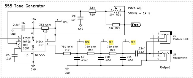
The original output square wave is pitch adjustable using a potentiometer. Figure 1 is the schematic for the 555 Tone generator, which is enabled at the reset pin by signals from other Digi-Keyer circuits. Wave samples are taken from test points TP4-TP6.
 Figure 1. 555 tone circuit with test points.
Waveform transformation
A 750 ohm resistor on the output of the 555, along with a 0.22uf capacitor at TP4, makes up the first transformation from a perfect square wave to a “shark tooth” shape. See (Figure 2). Another resistor/capacitor combo at TP5 results in a “sawtooth” wave followed by a more sinusoidal wave at TP6. The final output capacitor gives the wave a more defined sinusoidal shape and decouples any DC signals. The addition of the resistors also attenuates the output to headphone levels that, along with the wave shaping creates pleasant tones.
 Figure 2. Test point waveforms.
Summary
Sampling each test point using headphones with built-in volume control is a great way to experience the harshness of the square wave as compared to the smoothness of the quasi-sine wave. This example uses simple passive devices to alter the square wave. More elaborate circuits may be constructed using counters or op amps using the Wien bridge configuration.
Resources
Updating the Original Digi-Keyer
Interested in building the Digi-Keyer and learning how it works? DigiKey provides the full set of plans, bill of materials, programming code, PCB files, and more in this repository:
https://media.digikey.com/pdf/Project%20Repository/Digikeyer.zip

Have questions or comments? Continue the conversation on TechForum, DigiKey's online community and technical resource.
Visit TechForum


