An Understanding of How LiDAR Works Shows the Importance of Careful TIA and Comparator Selection
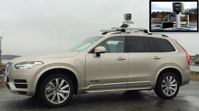
Light detection and ranging (LiDAR) has come to be most widely associated with the field of automotive design, where dreamers believe it can help realize a hands-free future. Specifically, digitally controlled optical signals are emitted from a 3D scanning instrument that detects the reflected signals to analyze the environment and assist in developing increasingly advanced driver assistance systems (ADAS). These dreamers had the right idea, though the implementations now vary widely from the classic “coffee can” approach (Figure 1).
 Figure 1: Automotive LiDAR sensors are critical components for ADAS, though they have evolved dramatically from the original coffee can approach. (Image source: Research Gate)
Early developers thought that a 360-degree picture was the way to go, but this solution was a bit pricey, preventing it from going fully commercial. Now it seems that automotive applications only require the ability to map in the forward direction, on-demand backward, and occasionally on the right and left, opening the door to more economical designs.
But I digress. Focusing on just automotive systems doesn’t do justice to LiDAR’s potential, so let’s take an overall LiDAR perspective, starting with an understanding of how it works.
Transimpedance amplifiers dominate the LiDAR core
The key to LiDAR is to measure an optical signal’s time-of-flight (ToF) from when the signal is emitted to when it returns as a reflection off an object. The technology works really well with a string of digital signals that are sent from a laser driver to a laser diode. The LiDAR system is looking for signal edges instead of signal frequency (Figure 2). This detection method relies on a good transimpedance amplifier (TIA).
 Figure 2: The laser diode emits a digital light pulse, and a TIA captures the return pulse. (Image source: Analog Devices Inc./Maxim Integrated)
In Figure 2, the LiDAR signal receiver circuitry comprises an Analog Devices/Maxim Integrated MAX40660 high-bandwidth TIA and an Analog Devices Inc./Maxim Integrated MAX40025 280 picosecond (ps) high-speed comparator (COMP) with ultra-low dispersion.
The MAX40660 forms the receiver link of the optical distance measurement chain. It has been designed for automotive LiDAR, so along with low noise, high gain, and low group delay, it features a fast output recovery from overload, an input current clamp, and an input-referred noise density of 2.1 picoamperes (pA). It has pin-selectable 25 kilohm (kΩ) and 50 kΩ transimpedance, and a wide bandwidth of 490 megahertz (MHz) (typical) with a 0.5 picofarad (pF) input capacitance.
The front end of this optical detection system is essentially a photodetector that relies upon careful design choices and implementation of best practices to effectively capture the optical signal. This translates to a TIA with unique bandwidth and noise specifications to enable fixed or moving object detection. The MAX40660 TIA’s wide bandwidth captures different physical condition details, and its low noise lowers the distortion level.
The MAX40025 high-speed COMP works as a one-bit, analog-to-digital converter (ADC). The overdrive dispersion is extremely low at 25 picoseconds (ps), making this comparator ideal for ToF distance measurement applications. With the MAX40025, the TIA optical signal converts to a clean “1” or “0” with the comparator’s typical 280 ps propagation delay.
Depending on the distance traveled, the light impinging on D1 may be bright or dim. Additionally, there may be contaminants in the atmosphere, and to confuse the system further, there may be interfering phantom lights.
To offset these effects, the effective use of LiDAR systems in the real world spans multiple disciplines. Automotive applications require the fusion of LiDAR, radar, and camera sensor systems. Mapping with drones and GPS provides researchers and engineers with 3D image details to lay down the groundwork for construction projects. Bathymetric or submarine LiDAR mapping defines the location of underwater structures. These applications, along with numerous others, have their own LiDAR construction requirements.
LiDAR and the electromagnetic spectrum
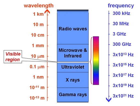
At the front end of the optical system in Figure 2, photodiode D2 senses the departing light for signal timing, while D1 senses the returning light. This electromagnetic optical signal can span from ultraviolet to infrared (Figure 3).
 Figure 3: The electromagnetic spectrum is the range of electromagnetic radiation, of which only a tiny fraction is in the visible range. (Image source: Cosmos)
Most LiDAR systems use infrared laser systems that use avalanche InGaAs silicon for D1 and D2, which have an optical wavelength of 1310 nanometers (nm) to 1550 nm. There are, however, LiDAR systems that use visible optical signals.
Conclusion
Among its many applications, LiDAR is a critical element along the path toward increasingly intuitive ADAS and eventually full hands-free automotive capability. As these technologies improve, the requirements around the supporting components for LiDAR continue to become more stringent. As discussed in this article, LiDAR signal receiver circuitry based around the MAX40660 high-bandwidth TIA and the MAX40025 280 ps high-speed comparator can form the foundation of a solid automotive LiDAR front-end.

Have questions or comments? Continue the conversation on TechForum, DigiKey's online community and technical resource.
Visit TechForum


