Achieving High Accuracy and High Reliability of Switch Components in DC Parametric Test
To solve various social issues such as realizing a safe and secure society, improving efficiency with robots, and conserving limited resources, various technologies are evolving in our world. Some of these advances are autonomous automobiles, higher-performance smartphones, robotic AI in factories, and IoT in home appliances. For these technological evolutions, it is necessary to realize more advanced componentry across all evolving markets. Test & measurement technology is extremely important in the advancement of semiconductors and is supported by high measurement accuracy and high reliability. Therefore, relays, which are often used to switch various measurement circuits in semiconductor test equipment, are also required to have these high-performance characteristics.

MOSFET relays have been widely utilized in semiconductor test equipment, though their performance is still not enough to meet all of the demands in the industry. It may be necessary to select other devices at the expense of stable on-resistance and size, depending on the application. For example, in a DC parametric test of a semiconductor inspection device, it is important to minimize the leakage current within the circuit to improve measurement accuracy. Therefore, MOSFET relays are difficult to use due to their innate leakage, and relays with physical contacts, such as reed relays, are still being used. The disadvantage then comes in the contact resistance of the reed relay. This resistance increases over time and requires regular maintenance to provide the quality signal transfer needed for testing. In addition, the reed relay package size is not small enough to meet demands for miniaturization. In this way, within the semiconductor DC parametric test, not all problems are being solved with existing switching devices.
 Table1. Required specification for relays under DC parametric test.
As a solution to this problem, OMRON has developed the T Module (G3VM-21MT / -61MT / -101MT). This component is a compact semiconductor relay module with a T switch function. This solution provides a long life and stable ON-resistance characteristics while achieving a minimal leakage current (ILEAK ≤ 1pA), comparable to that of a reed relay.

Value of the T-module (G3VM-21MT/-61MT/-101MT)
- Very small leakage current (ILEAK ≤ 1pA) for highly accurate measurements
- Very small package for space-saving and high-density integration (5 mm x 3.75 mm x 2.7 mm)
- Long life due to no physical contacts
- Good linearity for low signal distortion
Application examples
- ATE interface boards
- DC Parametric measurement unit
- Switching matrix unit
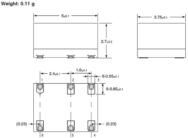 Figure 1: Omron T-module Outline Dimensions. (Image source: Omron)
 Figure 2: Omron T-module Terminal Arrangement (TOP VIEW). (Image source: Omron)
T switch function of T-module
As shown in Figure 3, this function exists by utilizing three MOSFET relays in a T formation circuit to minimize leakage current of the output main line (between pins 4 and 6).
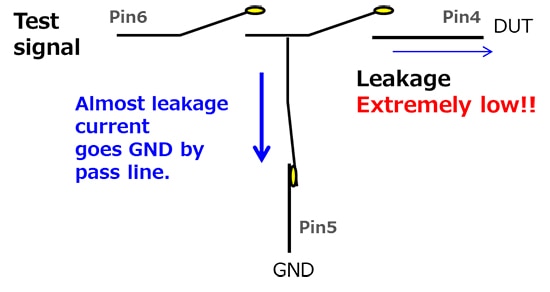 Figure 3: T switch function. (Image source: Omron)
Performance comparison between existing switching devices
OMRON has created the reference design board (Figure 4) which uses the switching circuit of the DC parametric test displayed in Figure 5. The data generated by this board compares the outputs and measurement accuracy of three different relay types: T modules, reed relays, and MOSFET relays.
 Figure 4: Reference design board with three different relay types. (Image source: Omron)
 Figure 5: Block diagram for measurement system. (Image source: Omron)
ILEAK test result
From the leakage current test results derived from the reference board, very similar levels of leakage can be seen in both the T-module and Reed relay. The outlier component is the MOSFET relay, which still leaks some current into the circuit.

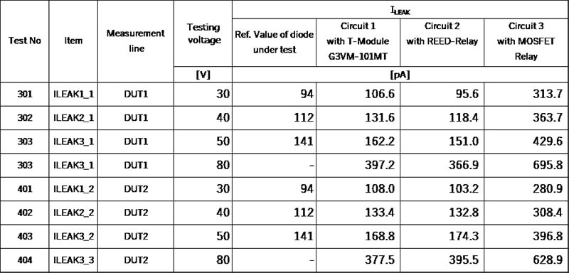 G3VM-101MT reference design board testing result (DUT: 1N3595)
 Figure 6: Example in case of leakage current measurement (DUT1). (Image source: Omron)
Note: This reference design (Figure 6) compares leakage current values (ILEAK) of one DUT (Diode) against 3 measurement circuits utilizing different relays (Circuit1: T module, Circuit2: Reed relay, Circuit3: MOS FET relay) using 2 Source Measurement Units. Ch1 adds test voltage as V source. Ch2 measures voltage from an amplifier for small current measurement then calculates the final output current value.
VF test result
A VF characteristics test result example with this reference design is shown below. The result shows the same level of accuracy between circuits with T-module, Reed relay, and MOSFET relay, and nearly the same value as compared to the reference DUT diode specification.
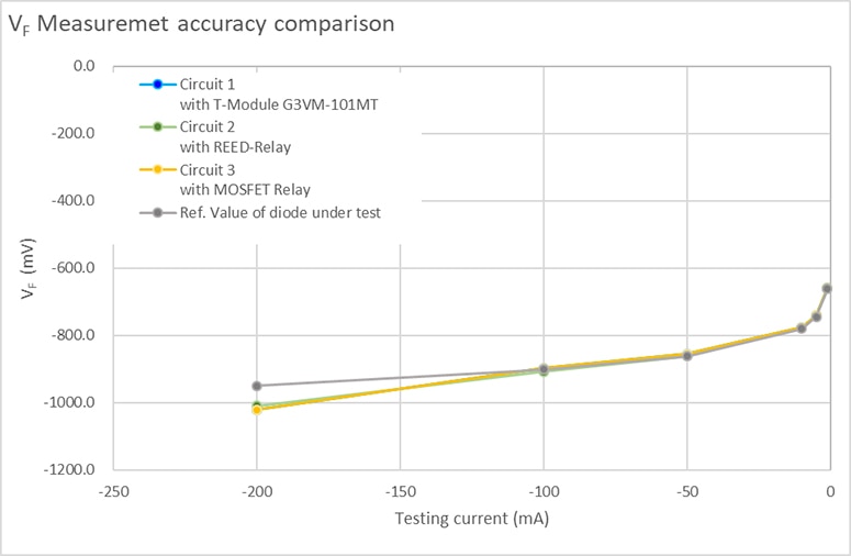
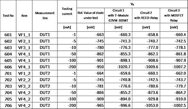 G3VM-101MT reference design board testing result(DUT: 1N3595). (Image source: Omron)
 Figure 7: Example in case of VF characteristics measurement (DUT1). (Image source: Omron)
Note: This reference design (Figure 7) compares VF of one DUT (Diode) against 3 measurement circuits utilizing different relays (Circuit1: T module, Circuit2: Reed relay, Circuit3: MOS FET relay) using 1 Source Measurement Unit. Ch1 adds the test current as I source and measures the voltage.
By using OMRON's T module, engineers can realize a solution that achieves both measurement accuracy and long-term reliability in DC parametric testing. This product’s goal is to improve society’s ability to continue to pursue great technological advances.

Have questions or comments? Continue the conversation on TechForum, DigiKey's online community and technical resource.
Visit TechForum


