Why and How to Apply GaN Field Effect Transistors for Efficient, Higher Voltage, Switch-Mode Power Applications
Contributed By DigiKey's North American Editors
2023-01-26
Power efficiency is a priority for electronic systems in the face of both societal and regulatory requirements. In particular, for applications ranging from electric vehicles (EVs) to high-voltage communications and industrial infrastructure, power conversion efficiency and power density are critical for design success.
To meet these requirements, designers of switch-mode power systems need to shift from using classic silicon (Si)-based metal oxide field effect transistors (MOSFETs) and insulated gate bipolar transistors (IGBTs), as they are quickly approaching their theoretical limits.
Instead, designers need to consider devices based on wide-bandgap (WBG) materials such as gallium nitride (GaN). GaN devices switch faster than Si devices, handle higher voltage and power levels, are much smaller for a given power level, and operate with much higher efficiency.
This article will examine the basics of GaN FETs, show their advantages over traditional Si devices in switch-mode power circuits, introduce real-world examples from Nexperia, and discuss their application.
The basics of GaN FETs
The fundamental elements in power conversion circuits are high-voltage semiconductor switches. Designers have been focused on improving the performance of these devices by: decreasing conduction losses by reducing on state series resistance, decreasing switching losses by increasing the transition speeds, and reducing parasitic effects. These design efforts have, in general, been successful for silicon MOSFETs and IGBTs, but the rate of improvement has been slowing as the operation of these devices reach their theoretical limits.
As a result, the past several years have seen the introduction of WBG devices using silicon carbide (SiC) and GaN, to the point that they have reached volume production. These devices offer higher operating voltage ranges, faster switching times, and higher efficiency.
The bandgap of a semiconductor is the minimum energy that is required to excite electrons to free them from their bound state into a free state to conduct electricity (Table 1).
|
Table 1: A summary of the key properties that distinguish wide-bandgap semiconductors—such as GaN and SiC—from Si. (Table source: Art Pini)
Devices made with wide-bandgap semiconductors can operate at much higher voltages, frequencies, and temperatures than conventional semiconductor materials like Si. The wider bandgap is particularly important for allowing devices to operate at much higher temperatures. The high temperature tolerance means that, under normal conditions, these devices can be operated at much higher power levels. WBG semiconductors with a higher critical electric field and higher mobility have the lowest drain-source on-state resistance (RDS(ON)), which reduces conduction losses.
Most wide-bandgap materials also have high free-electron velocities, which allows them to work at higher switching speeds.
Compared to Si, which has a bandgap of 1.12 electron volts (eV), GaN and SiC are compound semiconductors with bandgaps that are around three times higher at 3.4 eV and 3.3 eV, respectively. This means that both can support higher voltages and higher frequencies.
The higher electron mobility of GaN makes it much more suitable for high-performance, high-frequency applications. The faster switching speeds and higher operating frequencies enabled by GaN power FETs result in improved signal control, passive filter designs with higher cutoff frequencies, and lower ripple currents. This allows the use of smaller inductors, capacitors, and transformers, resulting in redued overall size and weight.
GaN FETs are called high electron mobility transistors (HEMT). The high electron mobility is a function of the FET structure (Figure 1).
 Figure 1: A cross-sectional view of a GaN FET based on an Si substrate. (Image source: Nexperia)
GaN FETs utilize existing silicon CMOS production facilities, making them cost-effective. A GaN layer is formed on the Si substrate by depositing a seed layer and a graded layer of GaN and aluminum gallium nitride (AlGaN) as an isolation layer (not shown in the diagram) before the pure GaN layer grows. A second AlGaN layer is deposited on top of the GaN layer. This sets up a piezoelectric polarization, with an excess of electrons being generated immediately below the AlGaN, which is a highly conductive channel. This excess of electrons is known as a two-dimensional electron gas (2DEG). The name reflects the very high electron mobility in this layer.
A depletion region is formed under the gate. The operation of the gate is similar to an N-channel, enhancement mode power silicon MOSFET. A positive voltage applied to the gate of this device turns it on.
This structure is repeated multiple times to form a power device. The end result is a fundamentally simple, elegant, cost-effective solution for power switching.
To obtain a higher voltage device, the distance between the Drain and Gate is increased. As the resistivity of GaN 2DEG is very low, the impact on resistance by increasing the blocking voltage capability is much lower when compared to silicon devices.
GaN FETs can be constructed to operate in either of two configurations, enhancement mode or depletion mode. Enhancement mode FETs are normally off, so a positive voltage relative to the drain/source must be applied to the gate to turn the FET on. Depletion mode FETs are normally on, so a negative gate voltage relative to the drain/source must be applied to turn the FET off. Depletion mode FETs are problematic in a power system because a negative bias has to be applied to the GaN depletion mode FET before powering up the system.
One way around this issue is to combine a low-voltage silicon FET with a depletion mode GaN FET in a cascode circuit configuration (Figure 2).
 Figure 2: A low-voltage silicon MOSFET in a cascode configuration with a depletion mode GaN FET results in the robustness of the Si gate structure with the improved high-voltage clocking characteristics of the GaN device, as well as having—in the case of a depletion mode GaN FET—the composite device off at power up. (Image source Nexperia)
The cascode circuit uses the Si MOSFET gate structure which has the advantages of higher gate drive limits matched to existing MOSFET gate driver ICs, and the depletion mode GaN FET being off at power up.
One of the key features of GaN FETs is their high efficiency. This is due to: low series resistance, which lowers conduction losses; their faster switching times, which lowers switching losses; and their lower reverse recovery charge, which accounts for their low reverse recovery losses.
Using a common half-bridge boost converter topology, it is possible to compare the efficiencies of GaN FETs and Si MOSFETs (Figure 3).
 Figure 3: Shown is the schematic of a half-bridge boost converter used for comparing the efficiencies of MOSFETs and GaN FETs by exchanging transistors Q1 and Q2 with each type. (Image source: Nexperia)
The boost converter has an input voltage of 240 volts, the output is 400 volts, and the switching frequency is 100 kilohertz (kHz). The efficiencies and losses are compared over a power range of up to 3500 watts (Figure 4).
 Figure 4: A comparison of the efficiency and power loss between GaN FETs and MOSFETs in an identical circuit, showing the advantages of the GaN FETs. (Image source Nexperia)
The GaN FETs run about 20% higher in efficiency compared with the MOSFETs, and the power loss is lower by a factor of about three. At 2000 watts, the loss in the MOSFETs is about 62 watts; in the GaN FETs it is only 19 Watts. This means that the cooling system can be smaller, thereby improving the volumetric efficiency of the boost converter.
Less obvious is that the measurement was carried out to almost 3500 watts for the GaN FET due to its higher maximum voltage limit. As such, the GaN FET has a definite advantage.
Getting started with GaN for higher voltages
For higher voltage applications, Nexperia offers two 650 volt GaN FETs, the GAN063-650WSAQ and the GAN041-650WSBQ. Both are N-channel FETs that are normally off. The GAN063-650WSAQ is rated to handle a maximum drain-to-source voltage of 650 volts and can sustain a transient (with a pulse width of less than a microsecond) of 800 volts. It is rated for a drain current of 34.5 amperes (A) and a power dissipation of 143 watts at 25°C. The drain-to-source on-state resistance is typically 50 milliohms (mΩ), with a maximum limit of 60 mΩ.
The GAN041-650WSBQ has the same 650-volt maximum drain-to-source voltage rating with the same 800-volt transient limit. It differs in that it can handle a maximum drain current of 47.2 A and a maximum power dissipation of 187 watts at room temperature. Its typical channel resistance is 35 mΩ, with a 41 mΩ maximum.
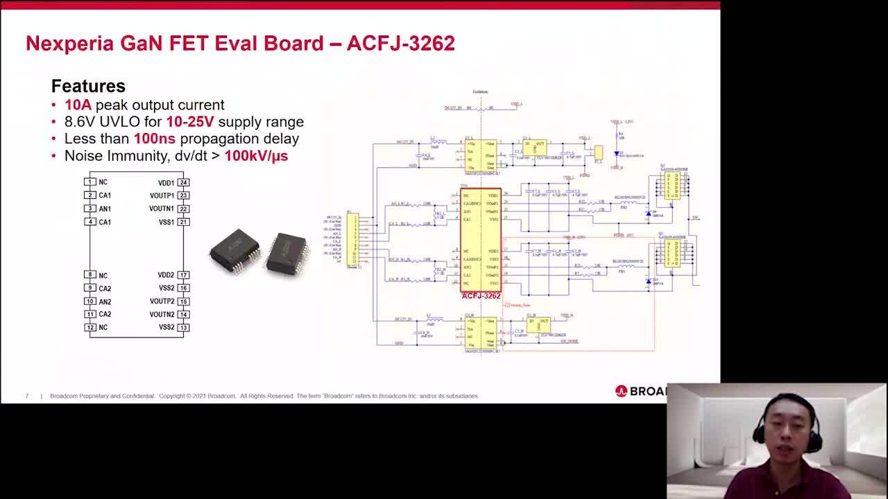
A Nexperia reference design using the GAN063-650WSAQ in a half-bridge configuration is shown in Figure 5.
") Figure 5: A recommended design for a half-bridge power stage using GAN063-650WSA GaN FETs. The schematic shows only the FET driver and half-bridge output stage, and related components. (Image source: Nexperia)
Figure 5: A recommended design for a half-bridge power stage using GAN063-650WSA GaN FETs. The schematic shows only the FET driver and half-bridge output stage, and related components. (Image source: Nexperia)
The schematic shows the Si8230 high/low dual isolated gate driver, which is used to drive the gates of the GaN FETs. The output of the gate driver is connected to the gate via a 30 Ω gate resistor, which is required for all GaN devices. The gate resistor controls the charging time of the gate capacitance, affecting the dynamic switching performance. The R-C networks between the drain and source of the FETs also aid in controlling the switching performance. The gate drive levels for the GaN FET are between 0 and 10 to 12 volts.
The high switching speed of the GaN FETs (typically in the 10 to 11 nanosecond (ns) range) requires careful layout to minimize parasitic inductance, and the use of RC snubbers to dampen ringing due to voltage and current transients. There are multiple RC snubbers (R17 through 19 and C33 through 35) in the design between the high-voltage supply and ground. The snubbers reduce ringing caused by the interaction of the GaN FET and the bypass network. Snubbers should be connected as close to the drain of the high-side FET as possible. They are implemented with surface-mount resistors and low effective series resistance (ESR) ceramic capacitors to minimize lead inductance.
The component network formed by R4, D1, C12, and C13 is a bootstrap power supply for the high-side gate driver. D1 should be a fast, low-capacitance diode because its junction capacitance contributes to switching loss. R4 limits the inrush charging current; a value in the range of 10 to 15 Ω works well.
Conclusion
From EVs to communications and industrial infrastructure, the need for greater power conversion efficiency and power density requires a shift from classic Si structures. As shown, GaN FETs provide a way forward for next-generation designs by offering higher operating voltages, faster switching times, and higher efficiency. Off-the-shelf components, supported in some cases by reference designs, help designers get projects up and running quickly.
Disclaimer: The opinions, beliefs, and viewpoints expressed by the various authors and/or forum participants on this website do not necessarily reflect the opinions, beliefs, and viewpoints of DigiKey or official policies of DigiKey.