Understanding, Selecting, and Effectively Using Current Probes
Contributed By DigiKey's North American Editors
2017-08-16
Editor’s Note: This article on current measurement and current probes is the third of a three-part series on probes and their proper use. Part 1, covered high-impedance passive probes. The second article discussed single-ended, differential, and high-voltage differential active probes. Part 3 will deal with current measurement and current probes.
There are three common techniques for measuring current using an oscilloscope. The first is using a resistor (sometimes called a current shunt) in series with the current being measured. The second is to use a current transformer. The third is to use a current probe. Since all three methods require that the current being measured pass through the measurement sensor they are all somewhat invasive.
The current probe, because it lets users measure a conductor’s current without having to unsolder it, is the least invasive technique. However, users need to understand some fundamental principles of current probes to get the most out of the latest probe designs.
This article will describe the various current measurement methodologies before introducing current probes and how to use them effectively.
The current shunt
The current shunt is generally designed into the circuit or related test fixture. The current is determined by measuring the voltage drop across the known resistance of the shunt. There is an engineering trade-off between the series resistance of the shunt and the desired sensitivity of the current measurement.
The idea is to get a reasonable voltage drop while at the same time not affecting the circuit’s performance. Also, the power rating of the shunt has to be sufficient for the current being measured. An example of a current shunt resistor is the Riedon RSA-10-100. This chassis-mounted resistor has a resistance of 0.01 Ω with a tolerance of ±0.25% and a power rating of 1 watt. The resistor power rating sets the maximum current at 10 amps, producing an output voltage of 100 millivolts. An oscilloscope is used to measure the voltage across the shunt. Most oscilloscopes have provisions to scale that voltage into an equivalent current (Figure 1).
Figure 1: The channel setup of a Teledyne LeCroy HDO4104 oscilloscope showing the rescale setup that allows vertical read out in Amperes based on the shunt resistor value (Image source: DigiKey).
The input channel setup for a Teledyne LeCroy HDO4104 oscilloscope is typical of many instruments in that it allows the vertical data to be rescaled. The Rescale controls permit the user to specify the units, Amperes in this case, and the rescale factor in Units/Volt. In the case of the RSA-10-100, the ‘Units per Volt’ setting is the reciprocal of the resistance value, or 1/0.01 = 100. There is also provision to add or subtract an offset current, something that might be needed for an active sensor. Once the Rescale setup is entered, the vertical scaling of the scope input channel will read out directly in Amperes, including measurement parameters and cursor readings.
Shunt resistors respond to both AC and DC currents with bandwidths limited by the resistors internal inductance and capacitance.
A complement to standard flat current shunt resistor is the coaxial or impulse current shunt. These devices arrange the shunt resistor(s) into a cylindrical geometry to minimize their inductance. Voltage contacts are brought out to a coaxial connector of suitable bandwidth.
Coaxial current shunts are available with bandwidths up to 100’s of MHz dependent on the resistor value and the maximum current rating.
The size of the coaxial shunt is proportional to maximum current rating and they are much larger than conventional flat current shunts.
Current transformer
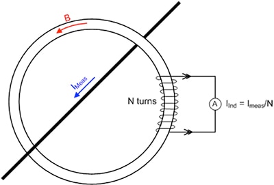
Magnetic sensing of current in a conductor is another possibility. The simplest magnetic based sensor is the current transformer (Figure 2).

Figure 2: The current transformer senses the current in a conductor passing through the opening in a ferrite core using a multi-turn secondary winding. (Image source: DigiKey)
The conductor carrying the current being measured (IMeas) is passed through the center of a ferrite core forming the primary winding of a transformer. The current induces a magnetic flux in the core proportional to the current. A sense winding of N turns is used to sense the magnetic flux. The current induced in the secondary is proportional to the turns ratio (ratio of the number of turns in the primary to the number of turns in the secondary winding, 1/N in this case).
The secondary current is converted to a voltage by passing it through a resistor, most commonly the 50 W termination of the oscilloscope. The input channel Rescale setting is set to N/50 amps/volt if the 50 W termination is used. The current transformer only works for AC signals. It cannot be used to measure direct currents.
Note that the conductor being measured must pass through the core. This can involve unsoldering the lead to insert it through the core. Some current transformers use split cores to facilitate insertion of the measured conductor.
Current probes
Current probes are designed to offer a convenient way of measuring current. They can be AC coupled, using current transformer technology or AC/DC coupled. In either case they include a split-core geometry that makes it easy to enclose the current carrying conductor without having to unsolder it.
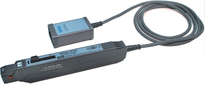
The Teledyne LeCroy CP030 is a good example of an AC/DC current probe capable of measuring up to 30 amps with a bandwidth of 50 MHz (Figure 3).

Figure 3: The Teledyne LeCroy CP030 is a 30 amp, DC to 50 MHz current probe. It is fully integrated with Teledyne LeCroy based oscilloscopes using the ProBus interface. (Image source: Teledyne LeCroy).
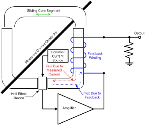
The CP030 uses a hybrid technology employing both a Hall effect device for the DC and low frequency AC signals and a current transformer for high frequency AC signals (Figure 4).

Figure 4: A functional block diagram of the CP030 AC/DC current probe. (Image source: DigiKey)
The CP030 is built on a split ferrite core, which enables quick insertion of the conductor carrying the current being measured.
It incorporates a Hall effect sensor inside a gap in the core and a feedback winding. The Hall effect sensor, when properly biased, produces an output current proportional to the flux in the core. This output is amplified and drives the feedback winding to obtain a zero-flux condition in the core. At this point, the current through the feedback winding is proportional to the flux due to the current-carrying conductor.
The output termination converts this current into a voltage. As the Hall effect sensor output decreases with increasing frequency, the feedback winding acts as a current transformer, accurately measuring the high-frequency components of the measured signal.
The sensitivity of the CP030 is 1 volt/amp. The probe communicates this to the oscilloscope using the ProBus interface. The scope automatically adjusts the scaling of the channel the probe is plugged into to read in Amperes (Figure 5).
Figure 5: The channel setup in a Teledyne LeCroy HDO 4104 oscilloscope with a CP030 connected. The probe is automatically recognized, as indicated in the Probe entry box. The correct scaling is automatically entered into the Units/V entry and the vertical units are set to Amperes. (Image source: DigiKey)
In addition to sensing and scaling the probe output, the oscilloscope includes a dialog box with all the controls related to the probe (Figure 6).
Figure 6: The setup dialog box for the CP030 probe, showing the controls for degaussing and Auto-Zeroing the probe. (Image source: DigiKey)
This includes the degaussing and Auto-Zero controls. Degaussing eliminates any residual flux in the probe’s core by applying a demagnetizing signal. Degaussing should be used before any critical measurement to insure the best accuracy. Auto-Zero control sets any offset of the probe’s output to zero volts when no current is present. Having these controls on the oscilloscope means that they do not take up any space in the probe body or interface box, making the probe smaller. The dialog box also identifies the probe and provides its salient specifications.
Common techniques to increase the usefulness of current probes
When measuring small currents, the sensitivity of a current probe can be increased by wrapping multiple turns through the primary (Figure 7A).

Figure 7: Increase the sensitivity of the current probe by wrapping multiple turns through the probe core (A). Make a differential measurement by enclosing multiple conductors through the probe core (B). (Image source: Teledyne LeCroy)
As in any transformer, the probe sensitivity will increase by the number of turns passing through the probe core. In the figure, there are four turns through the probe core increasing the sensitivity by a factor of four. This factor must be manually entered into the probe Rescale settings. Note also that the insertion impedance will increase by the square of the number of turns. In this instance the impedance will increase by a factor of sixteen. Since the measurement is intended for low current levels, the voltage drop across this impedance is generally low and should have a minimal effect on the measurement.
If multiple conductors are passed through the probe, the oscilloscope will read the net current (Figure 7B). This technique can be used to measure the differential current in two conductors. It can also be used to cancel a large offset current by passing a conductor with an equivalent DC current in the opposite direction. This can extend the range of the current probe.
Using third-party current probes
Many manufacturers supply current probes intended for the general oscilloscope market that do not use proprietary interfaces. These probes include a power source and controls for degaussing and adjusting the probe DC offset. An example is the CP6990O-NA, an AC/DC 40 A, 1.5 MHz stand-alone current probe from Cal Test Electronics (Figure 8).

Figure 8: The Cal Test Electronics CP6990-NA stand-alone current probe, with its associated accessories (Image source: Cal Test Electronics)
This current probe is battery powered and connects directly to an oscilloscope with the supplied BNC cable. The probe has dual sensitivity ranges, either 1 volt/amp or 100 millivolts/amp. The Rescale field on a Teledyne LeCroy HDO4104 would have 1 or 10 Units/Volt entered, respectively. The unit’s field should have “A” selected. The vertical scales for the selected channel will now be calibrated in Amperes.
Conclusion
Oscilloscopes can be used to make current measurements using current shunts, current transformers, or current probes. Regardless of the sensor used, the oscilloscope channel can be scaled to read directly in units of current.
The current probe is the easiest device to use due to its ease of connection. Current probes supplied by the oscilloscope manufacturer sense the probe and automatically scale the current data.

Disclaimer: The opinions, beliefs, and viewpoints expressed by the various authors and/or forum participants on this website do not necessarily reflect the opinions, beliefs, and viewpoints of DigiKey or official policies of DigiKey.


