Understanding, Selecting, and Effectively Using Active Oscilloscope Probes
Contributed By DigiKey's North American Editors
2017-07-21
Editor’s Note: This article on active probes is the second of a three-part series on probes and their proper use. Part 1 covered high impedance passive probes. This article will discuss single-ended, differential, and high voltage differential active probes. Part 3 will deal with current probes.
Active probes offer greater bandwidth and lower input capacitance than passive probes. In this article the characteristics of active probes relative to passive probes will be demonstrated. Both single-ended and differential probes will be studied, along with the proper use of probe accessories.
Why use active probes?
Passive probes are very suitable for measurement applications with bandwidths under 50 MHz. This is because passive probes have an input capacitance in the range of 9 or 10 picofarads (pF). This can load the device under test. These loading effects increase with increasing frequency. To avoid this loading effect, active probes interpose an amplifier between the passive probe’s compensated attenuator and the oscilloscope input (Figure 1).
The amplifier buffers the connecting cable and allows the cable to be terminated into its characteristic impedance, which is nominally 50 Ω. This isolates the probe from the capacitive loading of the cable and the input circuitry of the scope. The amplifier is designed to minimize input capacitance, with 4 pF being a nominal value. The compensated attenuator further reduces this capacitance. For a 10:1 attenuation, the expected input capacitance is about 0.4 pF. However, input protection circuitry and probe tip hardware add additional capacitance.
A typical active probe, the Teledyne LeCroy ZS1000 1 GHz single-ended active probe offers an input capacitance of 0.9 pF and an input resistance of 1 MΩ.
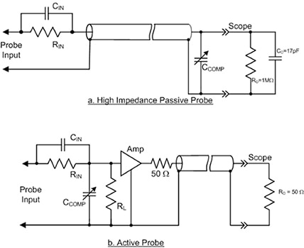
Figure 1: Simplified schematics of a high impedance passive probe and a single-ended active probe show the amplifier buffering the connecting cable and scope input, while offering a low input capacitance. (Image source: DigiKey)
The lower input capacitance extends the useful frequency range of the active probe. This can be seen in Figure 2, where the input impedance of a 10:1 high impedance passive probe is compared with that of the ZS1000.
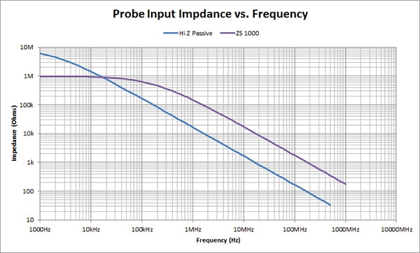
Figure 2: Input impedance as a function of frequency plotted for both a high impedance passive probe and a ZS1000 single-ended active probe. (Image source: DigiKey)
The ZS1000 has an input resistance of 1 MΩ and an input capacitance of 0.9 pF, compared to a 10 MΩ input resistance and 9.5 pF input capacitance for the passive probe. At frequencies above 20 kHz, the ZS1000 has a much higher input impedance, translating to less signal loading. At 500 MHz, the ZS1000 input impedance is 354 Ω, compared with 34 Ω for the passive probe.
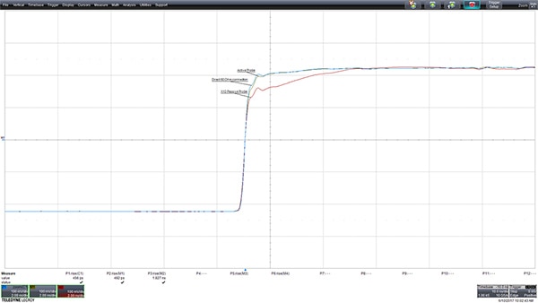
Perhaps the best way of comparing is to see the differences in response of the different probes to a fast edge (Figure 3).
Figure 3: The oscilloscope’s response to a fast edge using a 50 Ω direct connection, a passive probe, and a ZS series active probe. (Image source: Teledyne LeCroy)
The response of the 50 Ω direct connection is used as a reference waveform. The active probe response is almost indistinguishable from the reference waveform. The passive probe response has a rounded corner due to the higher input capacitance. Note the measured rise times. The rise time of the reference waveform (parameter readout P1) is 456 picoseconds (ps) compared to 492 ps for the active probe (P2). The passive probe rise time (P3) is 1.8 nanoseconds (ns).
Active probes will generally perform better than a passive probe with an equivalent bandwidth. It must also be kept in mind that active probes require power. Because of that, they almost always have proprietary connectors mated to a single manufacturer’s oscilloscope. In the case of the ZS1000 active probe, it is equipped with a Teledyne LeCroy ProBus interface, which powers the probe from the oscilloscope. The interface makes the probe integral with the oscilloscope so that the probe is sensed and fully controlled by the scope’s front panel.
Active probes also have a lower input voltage range than a passive probe. This requires caution to prevent damage to the probe. The ZS1000 probe has an input voltage range of ±8 volts and a non-destructive maximum voltage of 20 volts. This voltage range is greater than needed for any logic levels currently in use, making these probes ideal for high-speed logic measurements.
Probe accessories
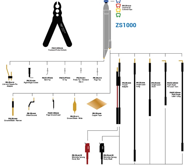
The ZS1000 probe comes with a number of accessories (Figure 4). Note that most of the probe tips and ground leads are quite small. Smaller physical size means lower capacitance and inductance, which in turn means less loading on the circuit under test. The longer ground leads and micro-clips are intended for low frequency applications, where their increased reactance does not affect the measurement.
Figure 4: The ZS1000 1 GHz active probe comes with a wide range of accessories, including longer ground leads for low frequency signals and various tips for easier test point access. (Image source: Teledyne LeCroy)
The standard probe tip is designed for general probing. The pogo tip and ground lead provide vertical compliance and assure positive contact without undue mechanical pressure. The IC tip is insulated, except at the very tip, to prevent inadvertent shorting of adjacent IC pins. The bent tip is ideal for probing under adjacent components and for applications where the probe must be held parallel to the board. The square pin adaptor conveys both the signal and ground lead to a standard 2.54 mm pin spacing.
The ground’s leads include both narrow and wide ground blades. Ground blades offer the benefit of low inductance ground connections. They are generally used with the copper tape pad. The pad is adhesive backed to stick to the IC. It is then soldered directly to the IC ground lead(s), providing a connection with a very low ground inductance. The offset ground is designed to connect to the probe ground socket and wrap around the probe head. This enables both the probe tip and ground to be closely spaced, while keeping the ground lead very short.
Differential probes
Differential probes measure the voltage difference between their two inputs. Unlike a single-ended probe, which measures the voltage between a single point and ground, the differential probe can measure between two inputs without the need for a ground connection. This is extremely useful when trying to make measurements on line side circuits in switched-mode power sources that are not ground referenced.
Since differential probes take the mathematical difference between the two inputs, signals that are common to both inputs, called common-mode signals, are cancelled out or greatly reduced in amplitude. This means that common bias levels, noise, and crosstalk that are common to both inputs can be canceled or at least reduced in amplitude.
A conceptual block diagram of a differential probe is shown (Figure 5). It includes a device under test modelled as a differential source with a common-mode element.

Figure 5: A conceptual diagram of a differential probe and a device under test modelled as a differential source with a common-mode element. (Image source: DigiKey)
The core element of the differential probe is the differential amplifier (diff amp). The diff amp output is the difference between the + and – inputs. Ahead of the diff amp, the circuit looks like two single-ended active probes. The differential probe inputs are shown connected to a generic differential source, which includes the two differential components Vp and Vn, and a common-mode source, Vcom.
The ideal differential probe works as follows: The voltage at the upper (+) probe input is Vp + Vcom. The voltage at the lower (-) probe input is – Vn + Vcom. Applying these inputs to the diff amp results in an output of Vp+Vn, assuming unity gain. The common-mode signal has now been eliminated.
The degree to which the common-mode signals are attenuated in a differential probe is specified as the common-mode rejection ratio (CMRR). The CMRR is the power ratio of the differential probe’s differential gain to its common-mode gain, expressed in decibels (dB). The CMRR is generally frequency dependent, decreasing with increasing frequency, and is usually specified at several frequencies.
The Teledyne LeCroy ZD1000 probe is an example of a 1 GHz bandwidth differential probe with a ±8 volt differential input range and a 60 dB CMRR at 60 Hz (Figure 6). It is meant for use with Teledyne LeCroy oscilloscopes. The probe’s differential input resistance is 120 kW with less than 1 pF differential input capacitance.

Figure 6: The ZD1000 differential probe is shown using a small IC adaptor. These probe tips are insulated on one side to prevent shorting adjacent IC pins. They also include low inductance resistive compensation to reduce inductive peaking. (Image source: Teledyne LeCroy)
The ZD1000 also includes numerous probe tip adaptors to meet the needs of many probing applications. It is good to keep in mind that the probing configuration for differential probes should be symmetrical, with identical adaptors on both inputs, to obtain the best CMRR possible.
High voltage differential probes
The key benefits of a differential probe are that the inputs are not referenced to ground and its ability to attenuate common mode signals. These features can also be useful in testing switched-mode power devices, in this case where the line side is not ground referenced. High-voltage differential probes, such as the Teledyne LeCroy HVD3106, are intended for this application (Figure 7).
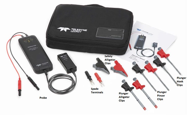
Figure 7: The Teledyne LeCroy HVD3106 probe and related accessories are designed for safe high-voltage probing, per IEC/EN 61010-31:2015. (Image source: Teledyne LeCroy)
The probe has a maximum differential voltage range of 1500 volts. This wide range is accomplished by using a 500:1 attenuation ahead of the differential amplifier. The probe achieves a CMRR of 85 dB at 60 Hz. Additionally, the physical configuration of the probe and its accessories are designed to carefully probe high voltages with safety rating per IEC/EN 61010-31:2015.
Conclusion
Active probes offer the benefits of increased bandwidth and lower probe loading. Differential probes add the value of ground isolation and the reduction of common mode signals. Proprietary interfaces fully integrate these probes into the scope user interface for easier setup and operation.

Disclaimer: The opinions, beliefs, and viewpoints expressed by the various authors and/or forum participants on this website do not necessarily reflect the opinions, beliefs, and viewpoints of DigiKey or official policies of DigiKey.


