Implementing Compact High-Performance Tracking and Traceability
Contributed By DigiKey's European Editors
2023-10-05
Factory automation and goods tracking system designers need optical barcode readers that can read code label types such as thermal print, laser engraving, or metal dot matrix. Decoding fast-moving and varying code labels on conveyor belts requires readers with low-latency, high-resolution image processing that can accurately decode damaged or dirty barcodes. The readers must reliably perform in harsh environments despite adverse lighting conditions, unpredictable label orientation, and uneven label geometry.
To address these needs while meeting cost and time constraints, industrial plant designers can use off-the-shelf barcode readers that are readily configurable to suit a wide range of target applications.
This article briefly discusses barcode standards and reader requirements before introducing suitable image-based barcode readers from Omron Automation and Safety that are easily configured in the field and are supported by various colored light and filter modules. The article discusses supported code standards, cabling, and how to configure the readers’ software.
Types of barcode standards
There are many types of barcodes, each with unique features and requirements. Figure 1 shows examples of linear (1D) barcodes, stacked linear, matrix (2D), and dot-code symbols, as well as photos of direct part marking (DPM) on different materials with different contrast and resolution quality.
![]() Figure 1: Code readers need to support a variety of codes, including linear (1D) barcodes, stacked linear barcodes, 2D matrix symbols, and dot-code symbols (top). DPMs have various contrast and resolution characteristics (bottom). (Image source: Omron)
Figure 1: Code readers need to support a variety of codes, including linear (1D) barcodes, stacked linear barcodes, 2D matrix symbols, and dot-code symbols (top). DPMs have various contrast and resolution characteristics (bottom). (Image source: Omron)
The 2D matrix on the right of Figure 2 illustrates the structure of the QR code: four square reference marks define the read orientation of the code label, while two zebra stripes signal the read clock. More than half of the cells contain the user data word; the rest serve as redundancy for error correction.
![]() Figure 2: The QR code adds error correction as well as reference and clock marks to the data word (left). Adjustable error correction levels can reconstruct 7% to 30% of the lost symbol area (right). (Image source: Omron)
Figure 2: The QR code adds error correction as well as reference and clock marks to the data word (left). Adjustable error correction levels can reconstruct 7% to 30% of the lost symbol area (right). (Image source: Omron)
If the QR code symbol is generated using the Reed-Solomon algorithm, the error correction can reconstruct 7% to 30% of the lost symbol area, depending on the level selected (Figure 2, right). According to ISO/IEC 24778, the Aztec code, a 2D dot matrix code for space-constrained applications, can be read in any orientation and specifies an adjustable error correction of 5% to 95%.
Image-based barcode reader integrating image processing
A good example of how advanced and capable readers have become is Omron’s compact MicroHAWK V430-F series of barcode readers. These readers can reliably read diverse matrix barcodes on a variety of surfaces in challenging factory environments. They use powerful error correction algorithms to decode damaged and incomplete symbols at speeds up to 60 frames per second (fps). Advanced optics combine monochrome or color image sensors with up to 5 megapixel (MP) resolution and various fixed or autofocus options.
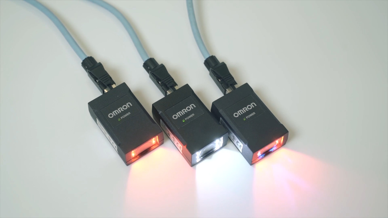
The V430-F000L12M-SRX monochrome barcode reader features a resolution of 1280 x 960 pixels (1.2 MP) (Figure 3). It integrates an autofocus lens with 1160 millimeter (mm) depth of field, eight red spotlight LEDs, and an 800 megahertz (MHz) image processor, all in a package measuring 44.5 (W) x 25.5 (H) x 56.9 (D) mm.
![]() Figure 3: Shown is the V430-F000L12M-SRX barcode reader with integrated illumination (left), and expanded with an LED ring and a diffuser module (right). (Image source: Omron)
Figure 3: Shown is the V430-F000L12M-SRX barcode reader with integrated illumination (left), and expanded with an LED ring and a diffuser module (right). (Image source: Omron)
The V430-F reader is IP67 rated and can be easily installed and configured on-site in industrial production areas. Onboard image processing captures 1D, 2D, and dot matrix codes, and detects DPMs in poor contrast conditions. Its error and image processing algorithms can decode damaged, dirty, blurred, or distorted code labels and output them as plain ASCII text.
Some important features of the V430-F family include:
- Support of code standards:
- ISO/IEC 15415: DataMatrix (ECC200, GS1), QR Code, Micro QR
- ISO/IEC TR 29158: DataMatrix (ECC200, GS1)
- ISO/IEC 15416: Code 128/GS1-12, UPC/EAN (JAN), ITF, Code 39, Code 93, Codabar
- ISO/IEC 16022: DataMatrix (ECC200, GS1)
- Three resolution options:
- 752 x 480 (0.3 MP) or 1280 x 960 (1.2 MP) monochrome, and 2592 x 1944 (5.0 MP) color
- 50 to 300 mm autofocus, 75 to 1200 mm autofocus, and fixed focus
- Focal length: wide angle, medium, or narrow/long
- Read cycle of 32 milliseconds (ms) at up to 60 fps
- Power supply of 5 to 30 volts, optional Power over Ethernet (PoE) (mode B), and a current consumption 180 milliamperes (mA) @ 24 volts
- Three input/output (I/O) control ports isolated by an optocoupler
- Communication via RS-232, TCP/IP, Ethernet/IP, or Profinet
- Daisy chaining of up to eight readers
- WebLink graphical user interface (GUI) for browser-based configuration and monitoring
The V430-F000W12M-SRP version uses a wide-angle lens and offers Plus Mode in its image processing firmware instead of X-Mode error correction. Plus Mode is suitable for high-contrast codes such as labels, whereas X-Mode’s aggressive symbol positioning, analysis, and reconstruction algorithms make it suitable for all labels, including low-print-grade codes and DPM. The F430 series devices are dual function, meaning they can operate simultaneously as a barcode reader and as a vision inspection system.
Add-on modules improve contrast
The F430 series comes with a variety of options to suit the application. For example, easy to install add-on modules such as ring lights (V430-AL) with eight or 24 LEDs in red, white, blue, or IR extend the contrast range of the barcode reader. In addition, color and polarization filters and diffusers (V430-AF) reduce stray light and glare from glossy surfaces (Figure 4).
![]() Figure 4: Diffusers and polarizing filters reduce reflections and stray light to improve contrast and reduce reading errors. (Image source: Omron)
Figure 4: Diffusers and polarizing filters reduce reflections and stray light to improve contrast and reduce reading errors. (Image source: Omron)
Connecting the barcode reader
The V430-F barcode reader has two M12 sockets and several connection options (Figure 5). The communication socket allows a host PC to read the decoded data via Ethernet/IP, TCP/IP, or Profinet, configure and monitor the barcode reader, and optionally supply power via PoE (mode B). The second plug connects to a programmable logic controller (PLC) for process control and includes a trigger input, an RS-232 interface, and three I/O switching signals. It is also used to supply power to the V430-F. Reading of the decoded data, configuration, and monitoring of the barcode reader can also be done via the V430-F’s RS-232 terminal.
![]() Figure 5: The V430-F barcode reader connectivity options include Ethernet, I/O control lines, RS-232, and power supply lines. (Image source: Omron)
Figure 5: The V430-F barcode reader connectivity options include Ethernet, I/O control lines, RS-232, and power supply lines. (Image source: Omron)
Omron offers configured Ethernet, I/O, and RS-232 cables for the V430 series (V430-W). When installing the V430-F in conjunction with peripheral components (such as a photosensor, an auxiliary LED light, and a power supply), the 98-000103-02 interface provides a useful four-way distribution point.
The WebLink user interface
The WebLink server integrated with the barcode reader provides the user with a GUI that is called up by entering http://192.168.188.2 into a browser. From here, the designer can control, monitor, configure, and read out the V430-F.
![]() Figure 6: The V430-F can be controlled, read out, and configured via the WebLink user interface. (Image source: Omron)
Figure 6: The V430-F can be controlled, read out, and configured via the WebLink user interface. (Image source: Omron)
The <Start> tab contains model-specific information for all connected readers and is the starting point for creating configuration profiles. The <Setup> tab displays important configuration settings on the left, while the middle area shows the camera image and offers image processing tools to define the barcode capture area. On the right, an output window continuously displays decoded barcode data words, which can also be tracked via the WebLink terminal or read out via the RS-232 interface.
Configure parameters
To significantly accelerate the decoding, designers can precisely delimit the detection area, defining the expected code types and optimally setting the image processing algorithms. They can also modify the output format of the decoded data word and insert, swap, or extract characters.
Using K-commands via the command line of the terminal or by directly changing values in the WebLink menu item <Advanced Settings>, designers can configure parameters for the following functional areas: Camera Setup, Communications, Read Cycle, Symbologies, I/O, Symbol Quality, Match String, Diagnostics, Image Storage, and Configuration Database.
Once the window of interest (WOI) section is made in the camera viewing area, all relevant code-label areas, referred to as region of interest (ROI), are defined inside. Up to ten such ROIs can be configured code-specifically in the configuration database. In <Run> mode, the V430-F can switch between these parameter sets.
Various special algorithms can improve poor symbol quality and are configured via the <Advanced Decoding Parameters> menu item:
- 2D Damaged Mode can decode symbols with distorted grid alignment or bad cell registration. Figure 7 in the upper left corner shows how it works. The feature can be enabled via serial command <K567,1> (0/1 = disabled/enabled).
- Attempt Morphology Manipulation applies morphology dilation or erosion and attempts to decode. The upper right corner of Figure 7 shows how it increases the signal strength and reduces noise. The algorithm is enabled via serial command <K568,1>.
![]() Figure 7: Image processing algorithms such as Damaged Mode, Morphology, and Scale Up/Down make it possible to decode even poor image quality. (Image source: Omron)
Figure 7: Image processing algorithms such as Damaged Mode, Morphology, and Scale Up/Down make it possible to decode even poor image quality. (Image source: Omron)
- Curved 2D is designed for Data Matrix and QR Code symbols.
If the length ratio between the red and green lines, shown in Figure 8, is greater than 20:1, the Curved 2D algorithm will be activated. The function is enabled via serial command <K563,1>.
![]() Figure 8: The Curved 2D image processing algorithm automatically detects curved code labels and rectifies them before decoding. (Image source: Omron)
Figure 8: The Curved 2D image processing algorithm automatically detects curved code labels and rectifies them before decoding. (Image source: Omron)
- Symbol Quality will output detailed evaluations in grades from A to F according to ISO/IEC 15416. Each single parameter can be enabled separately using the serial command <K726, aperture, overall, edge determination, decode, contrast, minimum reflectance, minimum edge contrast, modulation, defects, decodability, and quiet zone>. The serial command <VAL4> responds with a text report that summarizes the grading of ISO/IEC15416 (Table 1).
![]() Table 1: The serial command <VAL4> responds with a text report that summarizes the grading of ISO/IEC15416. (Table source: Omron)
Table 1: The serial command <VAL4> responds with a text report that summarizes the grading of ISO/IEC15416. (Table source: Omron)
Conclusion
The compact, image-based V430-F Series barcode readers reliably decode a wide variety of code standards on different surfaces and at high speeds in challenging factory environments. As shown, the powerful integrated image processing is readily configured via a browser, allowing designers to get a barcode reader up and running without specialized image processing experience.
Disclaimer: The opinions, beliefs, and viewpoints expressed by the various authors and/or forum participants on this website do not necessarily reflect the opinions, beliefs, and viewpoints of DigiKey or official policies of DigiKey.