

How to Extend the Range of 2.45 GHz Wireless Systems
Contributed By DigiKey's North American Editors
2017-07-07
The widely used 2.45 GHz short range radio systems such as Bluetooth low energy and zigbee are mature technologies that are particularly suited to Internet of Things (IoT) applications. While radios in this band do have good wall penetration and range properties, challenges arise in applications such as smart lighting where some nodes can be located far from the transmitting hub, forcing system designers to consider their range extension options.
Solutions to boost the range of these systems include mesh networking, whereby signals are relayed from one node to the next, or technologies such as Bluetooth 5’s error correction algorithm, which limits bit error rate (BER). However, mesh networking adds complexity, and Bluetooth 5’s range extension comes at the cost of reduced data rates. See, “Bluetooth 4.1, 4.2 and 5 Compatible Bluetooth Low Energy SoCs and Tools Meet IoT Challenges (Part 1).”
An alternative solution to increase range is to boost the radio’s “link budget” by teaming low noise amplifiers (LNAs) and power amplifiers (PAs) with RF chips. Designing in amplification is eased by selecting a RF front-end module (FEM) that comprises the LNA, or LNA + PA, RF switches, and logic in a pre-assembled and tested package.
There are some drawbacks to this solution, however, including increased cost and size, and greater power consumption. The designer must also consider U.S. FCC and other international regulations regarding transmission power in the unlicensed RF bands.
This article describes how RF FEMs increase the range of short range radio systems for IoT applications, discusses the drawbacks compared with alternatives, and provides application examples to illustrate the design process.
2.4 GHz operation trade-offs
A radio technology such as Bluetooth low energy or zigbee is based on a series of trade-offs that add up to limit range. First, the technology takes advantage of the “2.4 GHz” (centered on 2.45 GHz) Industrial, Scientific, and Medical (ISM) license-free band, which is recognized globally and is free for use by any party.
An initial trade-off is that while gigahertz frequencies support greater bandwidth, range is proportionally reduced. This means that for the same power output, 2.4 GHz radio signals don’t travel as far as those from a radio operating at 915 MHz (an alternative U.S. ISM frequency).
A second trade-off is that because it shares a band with many other radio sources, a 2.4 GHz ISM band radio faces restrictions on transmitter power. The rules are complex, but essentially dictate that peak transmit power, measured at the antenna input of a frequency hopping system with less than 75 but at least 15 hopping frequencies (Bluetooth low energy has 40), must be limited to +21 dBm, with a reduction in output if the isotropic antenna gain is larger than 6 dBi. This allows a maximum equivalent isotropic radiated power (EIRP) of +27 dBm.1
Thirdly, Bluetooth low energy and zigbee are designed to limit power consumption to maximize battery life. Such an attribute suits applications with many nodes, such as wireless lighting in a large office building because it lowers maintenance. Much of the power is conserved by limiting the time the radio is in a high-power transmit or receive state, but RF chip makers also conserve energy by limiting their Bluetooth low energy transmit power to +4 dBm (typically, and occasionally to +8 dBm, well below the +21 dBm allowed in the regulations).
The signal to noise ratio (SNR) is a measure of the ability of a receiver to correctly extract and decode a signal from the ambient noise. At a threshold SNR, the BER exceeds the radio’s specification and communication fails. A Bluetooth low energy receiver, for example, is designed to tolerate a maximum BER of only around 0.1%. SNR is a function of energy-per-bit to noise-density ratio (Eb/No), data rate (R), and receive bandwidth (B), according to the formula:
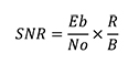
Contemporary Bluetooth low energy and zigbee transceivers maximize SNR by combining high receive sensitivity with adjustable output power to increase the link budget. Modern 2.4 GHz SoCs such as Nordic Semiconductor’s nRF52832 and Texas Instruments’ CC2538 offer similar maximum link budgets in the 100 to 110 dBm range. Depending on the application and how well the wireless product’s RF circuitry and antenna has been designed, such chips help achieve a range of perhaps 80 to 100 meters in perfect conditions, and 10 to 30 meters in a typical dwelling where RF radiation can be absorbed by walls and ceilings, and where interference from other 2.4 GHz sources can occur. In a large home, a wireless lighting node, for example, could easily be situated at the limit of a controller hub’s range, undermining reliable performance and future system scalability.
Boosting range
There are several alternatives for boosting range in Bluetooth low energy or zigbee applications. One is to employ a mesh network whereby signals are forwarded from node to node ensuring the outer reaches of the system can never be out of range. Mesh networking also offers the advantages of built in redundancy (a failed node can’t cause a system to fall over because signals can easily be rerouted) and simple scaling. The downside is a major increase in complexity and project overheads.
Another solution is to build in error correction to packet transmission to hold down BER in circumstances when noise would normally overwhelm the signal. This is the technique used to boost Bluetooth low energy’s range in the latest version (5) of the technology. The downside is the corrected packets demand greater system overheads compromising bandwidth.
A third option is to boost SNR, which in turn will enhance link budget and range. Assuming a designer has already adopted good RF circuit design principles to extract the optimum performance from a standard RF SoC or module, employing an RF FEM is the next step. See, “Bluetooth 4.1, 4.2 and 5 Compatible Bluetooth Low Energy SoCs and Tools Meet IoT Challenges (Part 2).”
A transceiver’s sensitivity to a received signal is determined in part by its noise figure (NF), which quantifies its ability to process a signal in the presence of noise. Interfacing the transceiver with an LNA lowers NF and increases sensitivity.
Employing an assembled, tested, and verified modular RF FEM incorporating an LNA is the most practical approach for simple circuit integration. There is a wide choice of RF FEMs suitable for the job. Skyworks, for example, offers the SKY66113-11 for Bluetooth low energy, IEEE 802.15.4 and zigbee applications (Figure 1). The chip integrates a high-gain LNA, a transmit bypass path, and digital controls. Gain is typically 12 dB and the NF is 2 dB.

Figure 1: Skyworks’ SKY66113-11 integrates an LNA with digital controls. The device also incorporates bypass switches to enable system operation without the LNA if required. (Image source: Skyworks)
Consider a system comprising Nordic Semiconductor’s nRF52832 and the SKY66113-11. According to the specification, the RF chip has a maximum sensitivity of -96 dB and a maximum output power of 4 dB for a link budget of 100 dB. Nordic’s datasheet doesn’t include an NF figure, but a typical value for this class of chip is around 8 dB.
The NF of the system is therefore:
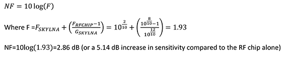
Such an increase will dramatically increase range. For comparison, in like-for-like applications, a 6 dB increase in sensitivity can lead to a near doubling of range.
Adding a power amplifier
In addition to boosting sensitivity using an LNA, range can simultaneously be boosted using a PA on the transmitter side. RF FEMs are available that integrate both LNA and PA. TI, for example, offers the CC2592, a range extender for its 2.4 GHz RF transceivers for Bluetooth low energy and zigbee. In addition to the LNA and PA, the CC2592 FEM contains further RF switches, RF matching and an on-chip balun for interfacing with devices such as the CC2538 zigbee/6LoWPAN (IEEE 802.15.4) transceivers (Figure 2).

Figure 2: It is straightforward to interface the CC2592 range extender to the CC2538 RF SoC. In this arrangement, the antenna and matching circuits are connected directly to the range extender rather than the RF SoC. (Diagram drawn using DigiKey Scheme-it®. Original source image from Texas instruments)
The CC2592’s LNA features a gain of 11 dB and NF of 4.7 dB, which boosts a typical system’s receiver sensitivity by 3 to 4 dB. In addition, the PA can boost transmitter output power by up to 22 dB. The setting of the PA will depend on the output power of the SoC (0, 4 or 8 dBm) and the output power constraints of the local regulatory environment. The output power is set by the 8-bit value in the CC2538 TXPOWER register.
Care should be taken when using a PA to extend a wireless product’s range. If range is a key design criteria, it can be tempting for the designer to crank the PA’s output to maximum to get the most from the system. This, however, could lead to amplifier saturation resulting in spurious emissions and harmonics that rise above regulatory limits. This in turn would make passing compliance testing impossible. It’s often wiser to lower the PA output and sacrifice some range to smooth the path to product compliance.
Further caution should be exercised when designing range extended wireless systems that might be subject to a wide operating range. An example is an unsheltered location. A combination of low temperature and low supply voltage can result in high spurious emissions. To avoid such a situation, TI recommends limits on transceiver output power (i.e. the input power to the CC2592’s PA) at low temperatures and supply voltages (Figure 3).

Figure 3: Limits must be placed on the transceiver output power (input power to CC2592 PA) at low temperatures and voltages to avoid spurious RF emissions. (Image source: Texas Instruments)
While low temperatures affect the CC2592’s PA, high temperatures have a detrimental effect on the unit’s LNA gain. At 20°C, the gain is 11 dB, while at 80°C it drops to under 10 dB (Figure 4).

Figure 4: High temperatures have a negative effect on the CC2592 LNA’s gain, shown as the black high-gain mode (HGM) line on this graph. The device also has a low-gain mode (LGM) not discussed in this article.) (Source: Texas Instruments.)
TI offers a CC2538-CC2592 Evaluation Module (EM) which can be used with its SmartRF06EBK tool to run a BER test and establish the maximum range of the CC2538-CC2592 system in a typical application by comparing it with a CC2538EM (the EM for the RF chip alone). It is easy to set up the test on the SmartRF06EBK including channel, TX power, number of packets (bits) and packet rate. The tool will run the test and display the BER/PER as a percentage (Figure 5). The same test can be run on the two EMs at varying distances to show how the CC2592 range extender limits the BER/PER as the range increases.

Figure 5: Screenshot from TI’s SmartRF06EBK illustrating BER/PER testing demonstrating how a CC2538-CC2592 system limits decoding errors as range increases. (Image source: Texas Instruments)
The key trade-off when boosting range using an RF FEM is power consumption (and a subsequent reduction in battery life). For example, in typical Bluetooth low energy operation without an RF FEM, the Nordic nRF52832 consumes around 7.5 mA TX (at 4 dBm) and 5.4 mA RX (1 Mb/s). The equivalent figures for the TI CC2538 running the zigbee protocol are 34 mA (at 7 dBm) and 24 mA.
When paired with the Skyworks SKY66113-11, the RX current consumption of the Nordic RF chip-based system rises to 9.4 mA. There is no increase in TX current because the RF FEM does not employ a PA. For the TI RF chip-based system, with the CC2592 PA operating at 22 dB, for example, the TX current rises from 155 mA to 189 mA, and with the LNA operational, the RX current rises from 4 mA to 28 mA.
Conclusion
While 2.4 GHz short-range wireless technologies are increasingly being employed in multimode industrial, commercial and consumer applications, greater range is frequently required. For systems where just a few outlying nodes represent the sum of the problem, improving the existing hardware’s link budget with RF FEMs represents a simple to implement and relatively inexpensive solution.
The hardware is simple to interface with RF chips, and at most, just a few simple firmware configuration commands are needed to get things working. The result is a doubling or even tripling of useful range from tens of meters for the standard technology to a hundred meters or more for the extended version.
As discussed, there are trade-offs as the RF FEMs increase solution size and cost. Some care is needed to ensure the system meets regulatory compliance, particularly regarding output power, and the designer must ensure there are no spurious emissions at low temperatures or supply voltages. Further, the range boosting amplification requires energy and consequently shortens battery life to some degree.
References
- “Bluetooth low energy regulatory aspects”, Bluetooth Special Interest Group, April 2011.
- “Extending 2.4 GHz ZigBee Short-Range Radio Performance with Skyworks SKY65336/SKY65337 Front-End Modules”, Skyworks, October 2009.
Disclaimer: The opinions, beliefs, and viewpoints expressed by the various authors and/or forum participants on this website do not necessarily reflect the opinions, beliefs, and viewpoints of DigiKey or official policies of DigiKey.

