How to Design Efficient Modular Power Delivery Networks for Tethered UAVs
Contributed By DigiKey's North American Editors
2023-02-17
Unmanned aerial vehicles (UAVs) or “drones” are increasingly used for heavy-duty applications such as ground reconnaissance for the military, firefighting, and agriculture. These and many other use cases demand the drone be in the air for long periods, so batteries are not an option. Instead, the drone is supplied with power through a tethered cable for the duration of its flight.
However, tethers introduce new challenges. A thicker tether offers lower electrical resistance but places a greater load on the drone, limiting its carrying capacity. Thin cables increase the electrical resistance, causing unacceptable power dissipation and voltage drop over the typically long lengths of drone tethers. Engineers are looking to overcome the losses associated with thinner cables by increasing the tether voltage up to 800 volts. Such an increase helps lower the current for a given power requirement.
The challenge then becomes handling the high voltage in the drone. The drone’s power distribution network must be capable of taking the high voltage and efficiently stepping it down to the lower voltages required by the UAV’s systems. Any power management solutions must be light and compact to minimize the impact on the load-carrying capacity of the vehicle.
This article discusses the benefits of high-voltage supply systems for tethered drones. It then explains why high-efficiency and high-power-density bus converter modules (BCMs) and zero-voltage switching (ZVS) step-down (“buck”) voltage converters are a good option when designing power distribution networks for tethered UAV applications. Example BCMs and ZVS buck converters from Vicor are introduced and used to help show how to design a light, yet efficient power network.
Higher voltages enable lighter cables
Tethers free designers from the restrictions that batteries impose on drones (Figure 1). The UAVs can remain airborne for long periods, assuming ground-based power is available, allowing them to operate in applications such as observation platforms or over-the-horizon radio relays. The downside is that the drone must hoist a potentially heavy cable aloft, which can limit both its operational range and its carrying capacity for payloads such as cameras or radio equipment.
 Figure 1: Drones can stay aloft for long periods using power supplied via a tether. (Image source: Vicor)
Commercial drones require several DC voltages for their various systems. For example, 48 volts is common for motors, while 12, 5, and 3.3 volts are typical for sensors, actuators, and control electronics. Thin, lightweight tethers help limit the weight load on the drone, but the cable’s higher resistance (resistance increases as cable cross-section decreases) can cause an unacceptably high voltage drop (defined as a voltage drop of greater than 3 to 5 percent of the source voltage at the far end of the cable) and power dissipation over long cable runs when using a 48-volt supply.
The cable’s voltage drop and power dissipation are proportional to the current it’s carrying rather than the voltage. So, for example, a commercial drone that requires a constant power of 1.5 kilowatts (kW) powered via a 48-volt supply will require a current of 1500/48 = 31.25 amperes (A). Identical power can be supplied by increasing the voltage, thereby lowering the current requirement and, subsequently, the voltage drop and power dissipation. For example, using an 800-volt supply requires a current of just 1500/800 = 1.9 A. Such a supply allows the designer to safely use a lightweight cable.
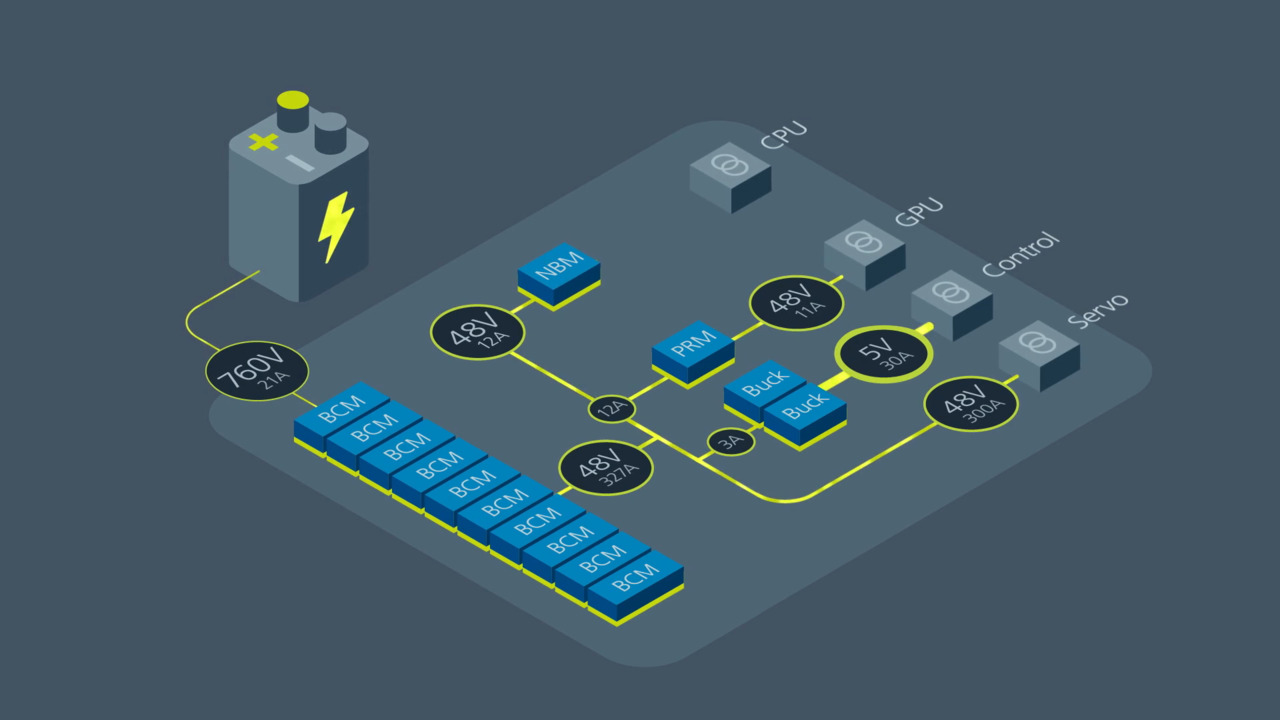
A power delivery network for a drone
To take advantage of higher voltage supplies and lighter tethers, engineers need to design power distribution networks that can safely and efficiently step down the high voltages carried in the tether to the working voltages needed for the drone’s systems.
Figure 2 shows an example of such a network. This network is built using BCMs and ZVS buck converters from Vicor.
 Figure 2: A power distribution network for a tethered drone. Note how the 48-volt bus used for ground-based systems is boosted to 800 volts in the tether and then reduced back to 48 volts at the drone. (Image source: Vicor)
In this example, a BCM converts the three-phase 208-volt AC supply to 48 volts DC for the drone’s ground-based computer systems. ZVS buck converters reduce the 48-volt supply to the 12, 5, and 3.3 volts used by the individual ground-based devices. The 48-volt DC supply is then stepped up by a second BCM to 800 volts to minimize voltage drop and power loss in the tether.
At the drone, a third BCM then reduces the voltage back to 48 volts. The power distribution network in the drone includes further buck converters to supply cameras, sensors, and logic devices with appropriate voltages.
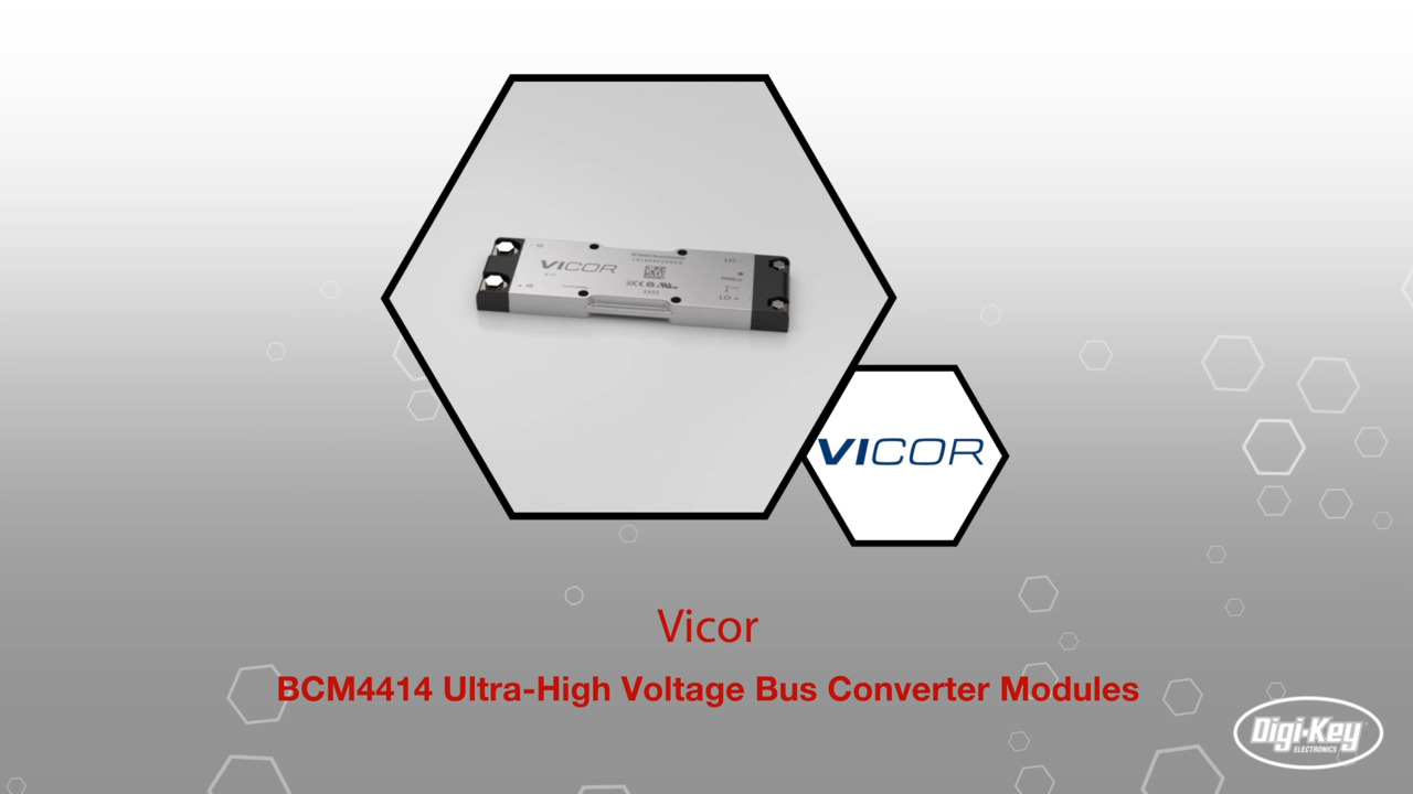
The suggested BCMs for this application are Vicor’s BCM4414VD1E5135C02 for the initial 208 volt AC to 48 volt DC conversion, and the BCM4414VH0E5035M02 for the 48 volt DC to 800 volt DC and back conversion.
The BCM4414VD1E5135C02 operates from a 260 to 400-volt bus and offers a low-side output of 32.5 to 51.3 volts. The device offers up to 35 A continuous low-side current, up to 49 watts per cubic centimeter (W/cm3) power density, and 97.7 percent peak efficiency (Figure 3).
 Figure 3: Vicor’s bus converter modules exhibit good efficiency across a wide low-side current range (TCASE = 25˚C). (Image source: Vicor)
The BCM4414VH0E5035M02 operates from a 500 to 800-volt bus and offers a low-side output of 31.3 to 50.0 volts, with a maximum continuous power output of 1.5 kW. Continuous low-side current, power density, and peak efficiency are identical to its sister product. The BCM comes in a 110.5 x 35.5 x 9.4-millimeter (mm) case and weighs 145 grams (g).
The Vicor BCMs also offer flexible thermal management options with very low top and bottom-side thermal impedances. By using the devices, the power system designer is able to reduce the size and weight of the tether, as well as the ground supply and the drone.
The Vicor BCMs are DC-to-DC power supplies, so the initial three-phase 208-volt AC input must be converted to DC before the first BCM in Figure 2. A suitable device for the AC rectification is a Vicor AC input module (AIM) such as the AIM1714VB6MC7D5C00 (Figure 4.) The AIM device can accept an 85-to-264-volt AC input and provide a rectified AC output with a current of up to 5.3 A and power up to 450 watts.
") Figure 4: The BCM requires a rectified AC input. A device such as Vicor’s three-phase AIM module provides a solution. (Image source: Vicor)
Figure 4: The BCM requires a rectified AC input. A device such as Vicor’s three-phase AIM module provides a solution. (Image source: Vicor)
Buck regulation with high power density and flexibility
Once the BCM in the ground station or the drone has regulated the voltage to 48 volts DC, ZVS buck converters are required to further step down the voltage for supply lines to the various systems. Particularly in the drone, the buck converters must feature high-power density and be efficient such that they form a compact and lightweight power supply. ZVS buck regulators are well-suited to the task.
The switching losses within conventional voltage regulator MOSFETs are a key source of inefficiency and have a negative impact on power density. ZVS addresses these losses and is a particular advantage for buck converters operating with a relatively high voltage input.
The mechanism of ZVS (also known as “soft switching”) is complex but can best be defined as conventional pulse-width modulation (PWM) power conversion during the MOSFET’s on-time, but with “resonant” switching transitions. Regulation of the output voltage is achieved by adjusting the effective duty cycle (and thus “on” time) by varying the switching regulator’s conversion frequency.
During the ZVS switch off-time, the regulator’s L-C circuit resonates, traversing the voltage across the switch from zero to its peak, and back down again to zero when the switch can be reactivated. In the process, the switching regulator’s MOSFETs’ transition losses are zero—regardless of operating frequency and input voltage—representing significant savings in power, and a substantial improvement in efficiency. (See “A Review of Zero-Voltage Switching and its Importance to Voltage Regulation”.)
Vicor produces a range of ZVS buck regulators integrated with control circuitry, power semiconductors, and support components in high-density LGA, BGA, and system in package (SiP) devices. The switching voltage regulators complement the BCMs used in other parts of the drone’s power distribution circuit. The ZVS buck regulators offer good power density and flexibility for high-efficiency point-of-load (PoL) DC-to-DC regulation. They can be used to efficiently step down the 48 volt bus to 3.3, 5, and 12 volts for the other drone subsystems.
Examples of ZVS buck regulators include the PI352x-00 family. The PI352x-00 regulators require only an external inductor, two voltage-selection resistors, and a minimal number of capacitors to form a complete DC-DC switch-mode buck regulator. All the regulators operate from a 30 to 60 volt input. There are three devices in the family: the PI3523-00, which provides a nominal 3.3 volt output (2.2 to 4 volt range) and up to 22 A; the PI3525-00, which provides a nominal 5.0 volt output (4 to 6.5 volt range) and up to 20 A; and the PI3526-00, which provides a nominal 12 volt output (6.5 to 14 volt range) and up to 18 A. The devices are supplied in an LGA SiP measuring 10 x 14 x 2.56 mm.
Adding ZVS regulators to the power density network
Some design work is required to optimize the performance of the ZVS buck regulators in the drone power distribution network. Figure 5 shows the external components required for each member of the PI352x-00 family.
 Figure 5: The Vicor ZVS buck regulator requires an external inductor, a resistor divider network to set the output voltage, as well as capacitors for filtering. (Image source: Vicor)
The devices each require an external inductor. Vicor has calculated the inductance value for the energy storage device to maximize efficiency. For the PI3523 and PI3525 regulators, a 230 nanohenry (nH) inductor is recommended, while a 480 nH inductor is recommended for use with the P13526.
While each member of the PI352x-00 family can directly handle the 48-volt DC input from the respective BCM (the input range for the buck regulators is 30 to 60 volt DC), setting the output voltage requires the selection of output resistors—REA1 and REA2—that together form a resistor divider network.
Regardless of output voltage, REA2 should be set to 1 kilohm (kΩ) for the best noise immunity. The value of REA1 can then be calculated from the following formula:
/REA2 Therefore, REA1 = REA2 x (VOUT – VREF)/VREF, Where VREF = VEAIN = 1 volt For example, for a 5 volt output, REA1 = 1000 x (5 – 1 )/1 = 4 kΩ")
In addition to inductor values, Vicor also recommends values for the CIN and COUT capacitors to ensure proper start-up and high-frequency decoupling for the power stage. The PI352x-00 family draws nearly all the high-frequency current from its low-impedance ceramic capacitors when the main high-side MOSFETs are conducting. Then, during the time the MOSFETs are off, the capacitors are replenished from the source. Table 1 lists the capacitor values and resultant ripple currents and voltages.
|
Table 1: Recommended values for the Vicor P1352x input and output capacitors at nominal line voltage and nominal trim. (Table source: Vicor)
To ensure optimal efficiency and low electromagnetic interference (EMI) with the PI352x-00 family, minimal trace resistance and high-current loop returns, together with proper component placement, is essential. Figure 6 shows the recommended layout for the regulator and external components. This is the layout adopted by the PI3526-00-EVAL1 PI352x-00 evaluation board.
 Figure 6: Optimum layout for the Vicor ZVS regulator, inductor, and input and output capacitors. (Image source: Vicor)
The blue loop in Figure 6 indicates the tight path between the input and output capacitors (and VIN and VOUT) for the regulator’s high AC return current, which aids efficiency.
Conclusion
To optimize the range and load capacity of drones, engineers have turned to high-voltage tethers. These minimize power dissipation and voltage drop in the cables. However, the high tether voltages need to be safely and efficiently regulated to bus voltages, and then reduced further to the supply voltages needed by the drone’s electronic systems.
High power density and efficient BCMs from Vicor provide an easy-to-implement solution for reducing and boosting the voltages between the ground station, tether, and drone. The BCMs are complemented by low switching loss ZVS buck converters, which offer 97 percent efficiency when stepping down the bus voltage to the 3.3, 5, and 12 volts needed for the drone’s various subsystems.
Disclaimer: The opinions, beliefs, and viewpoints expressed by the various authors and/or forum participants on this website do not necessarily reflect the opinions, beliefs, and viewpoints of DigiKey or official policies of DigiKey.