Why and How to Use a Component-Based Distributed Power Architecture for Robotics
Contributed By DigiKey's North American Editors
2020-11-19
The use of battery-powered robots is growing across applications such as factory automation, agriculture, campus and consumer delivery, and warehouse inventory management. For maximum operating time between charges, designers of these battery systems have always needed to be concerned about power conversion efficiency, as well as size and weight.
However, these concerns have become more critical as load capacities continue to increase and sensing and safety features such as vision, ranging, proximity, location, among others, add design complexity and physical weight. At the same time, the additional electronics processing required also consumes more power.
To maximize battery life in the face of these additional challenges, designers can turn to a component-based distributed power delivery architecture to power the motors, CPUs and other subsystems. In such an approach, each individual DC-DC power conversion component can be placed at the point of load (PoL) and optimized for high efficiency, small size (high power density) and overall performance. This approach can result in a lighter overall power system, enabling further performance gains for battery-powered robotic systems. Flexibility is also enhanced since power conversion components can be paralleled to easily scale as robotic power demands increase, and they also allow for the same power architecture to be deployed across a platform of various-sized robotic systems.
This article briefly outlines the power needs of several robotics applications including agricultural harvesting, campus and consumer delivery, and warehouse inventory movement. It will then review the benefits of using a component-based distributed power delivery architecture, and then introduce example DC-DC converter solutions from Vicor, along with evaluation boards and associated software to help designers get started.
Power requirements for robots
The power requirements for specific types of robots are determined by the application:
- Agricultural harvesting robots: Plant, maintain, and harvest produce (fruits, vegetables, grains) using automated vehicle guidance along with visual recognition and multiple environmental and soil analysis sensors. These large robotic vehicles are typically powered from a high-voltage DC source of 400 volts or more.
- Delivery robots: Last-mile consumer or campus delivery of various items. While payloads vary in size and weight, these robots are typically powered by 48 to 100 volt batteries and have longer run time requirements than the warehouse inventory moving class of robots.
- Warehouse inventory moving robots: Provide inventory management and order fulfillment tasks within large warehouse environments. This robot class is typically powered from a 24 to 72 volt battery source with opportunity charging performed on an as-needed basis.
Component-based distributed power architectures for robotics
This section reviews four examples of component-based distributed power architectures for robots ranging from a 15.9 kilowatt (kW) system for agricultural harvesting robots with a 760 volt battery pack down to a 1.2 kW system for warehouse inventory movement robots using a 48 volt battery pack. A common feature in three of these applications is a relatively high voltage main bus that distributes power throughout the robot, followed by one or more voltage step-down sections that deliver the needed power to the subsystems. A high-voltage power distribution bus results in improved efficiency and lower power distribution currents which allows the use of smaller, lighter and less expensive power cables. The fourth application shows the simplification that can result in smaller robots that use 48 volt battery systems.
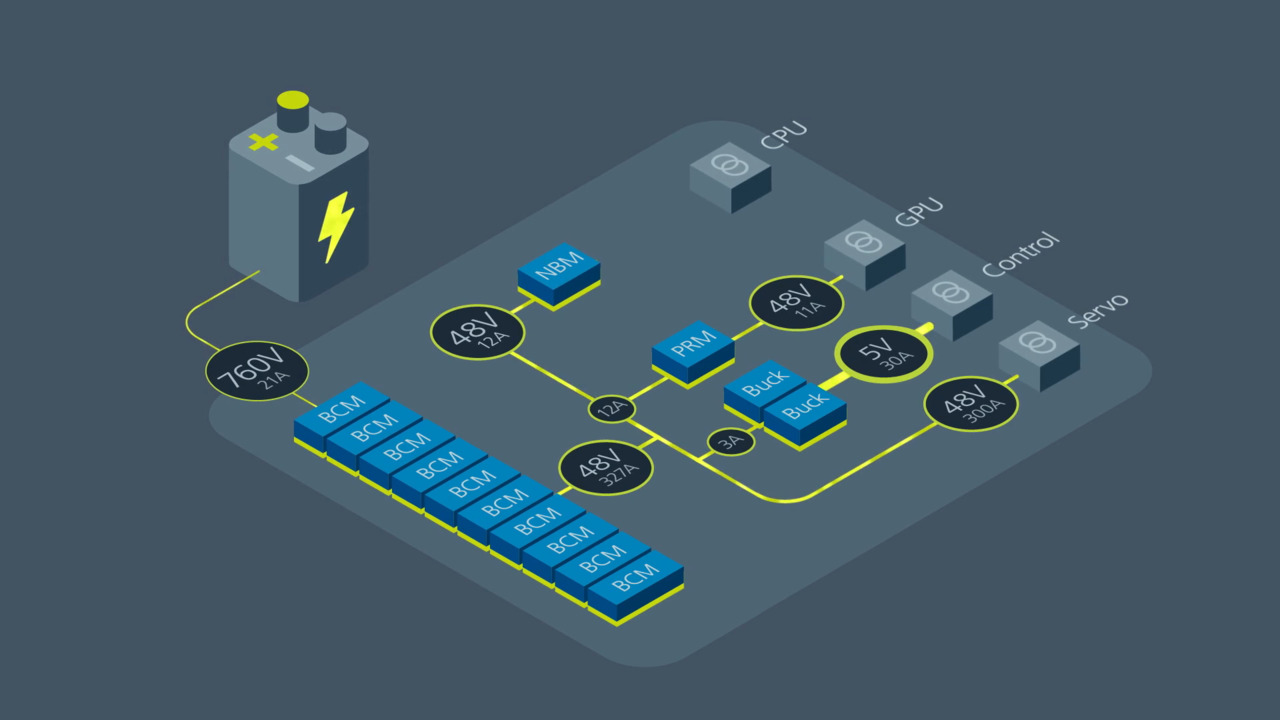
The power delivery network (PDN) for agricultural harvesting robots comprises a 760 volt main power bus (Figure 1). This is supported by a series of fixed ratio (unregulated) isolated DC-DC converters (shown as BCM modules on left) with an output voltage of 1/16 of the input voltage. These converters are used in parallel, enabling the system to be resized according to the needs of the specific design.
 Figure 1: This PDN for 15.4 kW agricultural harvesting robots comprises a 760 volt distribution bus supporting a network of lower voltage converters (DCMs, PRMs, NBMs, and buck. (Image source: Vicor)
Further into the network, a series of fixed ratio (NBM, upper middle) and regulated buck-boost (PRMs, center) and buck converters (bottom) power downstream, lower voltage rails as needed. In this design, the servo is driven directly from the 48 volt intermediate power bus with no additional DC-DC conversion.
The PDN for campus and consumer delivery robots shows the simplification that can result in medium power systems by employing a lower main power bus voltage (in this case, 100 volts), and adding regulation to the isolated DC-DC converters (DCMs) on the main power distribution bus to produce the 48 volt intermediate bus voltage (Figure 2).
 Figure 2: The PDN for campus and consumer delivery robots includes direct drive for the motor and an intermediate bus to power the remaining subsystems. (Image source: Vicor)
This approach enables the use of non-isolated buck-boost and buck DC-DC converters to power the various subsystems. In addition, the use of a lower voltage for the main power bus enables the motor drive to connect directly to the main bus, while the servo can connect directly to the 48 volt intermediate bus. Smaller campus and consumer delivery robots may incorporate a 24 volt intermediate bus voltage and either 24 or 48 volt servos, but the overall architecture is similar.
The PDN for warehouse robots using a 67 volt battery pack highlights the use of buck-boost non-isolated DC-DC converters (PRMs) on the main power bus (Figure 3). These converters provide efficiencies of 96% to 98% and can be paralleled for higher power needs. This architecture also features a fixed ratio, non-isolated DC-DC converter (NBM) to power the GPU, and non-isolated regulated buck converters powering the logic sections.
 Figure 3: The PDN for warehouse robots combines a 67 volt main power bus and a 48 volt intermediate power distribution bus. (Image source: Vicor)
For smaller robot designs using a 48 volt battery there is no need to generate an intermediate bus voltage, simplifying the design (Figure 4). The loads are powered directly from the battery voltage by direct conversion using various non-isolated DC-DC converters. The elimination of the intermediate bus in the power train increases system efficiency and reduces power system weight and cost.
 Figure 4: The PDN for warehouse robots using a 48 volt battery pack eliminates the need for an intermediate power bus, greatly simplifying the design. (Image source: Vicor)
Distributed power architecture design considerations
As shown above, designers must make numerous power system choices to optimize a component-based PDN for robotics. There is no “one size fits all” approach. In general, larger robots benefit from higher battery voltages which can result in higher power distribution efficiencies and smaller, lighter power distribution buses.
The use of isolated versus non-isolated DC-DC converters is an important consideration when optimizing overall system efficiency and minimizing costs. The closer the DC-DC converter is to a low-voltage load the more likely it is that the optimal choice will be a lower cost, non-isolated power component, increasing overall PDN efficiency. When appropriate, the use of lower cost fixed-ratio (unregulated) DC-DC converters can also contribute to higher PDN efficiencies.
Vicor offers DC-DC converters that are capable of supporting designers’ needs in a wide range of component-based distributed power delivery architectures, including the four outlined above. The following discussion focuses on specific devices that can be used in a power delivery system similar to the one described for campus and consumer delivery robots, as shown in Figure 2.
DC-DC converters for robot power systems
The DCM3623TA5N53B4T70 is an example of a DCM isolated and regulated DC-DC converter that can produce the 48 volt intermediate bus voltage from 100 volt battery power (Figure 5). This converter uses zero voltage switching (ZVS) technology to deliver a 90.7% peak efficiency and a 653 watts per cubic inch power density. It provides 3,000 volts dc isolation between the input and output.
 Figure 5: The DCM3623TA5N53B4T70 isolated and regulated DC-DC converter can produce the 48 volt intermediate bus voltage from 100 volt battery power. (Image source: Vicor)
Leveraging the thermal and density benefits of Vicor’s Converter-housed-in-Package (ChiP) packaging technology, the DCM module offers flexible thermal management options with very low top and bottom side thermal impedances. ChiP-based power components enable designers to achieve cost-effective power system solutions with previously unattainable system size, weight and efficiency attributes, quickly and predictably.
To start exploring the capabilities of the DCM3623TA5N53B4T70, designers can use the DCM3623EA5N53B4T70 evaluation board (Figure 6). The DCM evaluation board can be configured for various enabling and fault monitoring schemes, as well as to exercise various modes of trimming depending upon the application requirements.
 Figure 6: The DCM3623EA5N53B4T70 evaluation board enables designers to explore the capabilities of the DCM3623TA5N53B4T70 DC-DC converter. (Image source: Vicor)
The DCM3623EA5N53B4T70 can be used to evaluate DCMs in either a stand-alone configuration, or as an array of modules. It also supports evaluation of various enable, trim and fault monitoring options:
Enable options:
- On-board mechanical switch (default)
- External control
Trim options:
- Fixed trim operation (default): the TR pin is permitted to float at initial startup.The DCM disables output trimming and the output trim is programmed to the nominal rated VOUT.
- Variable trim operation, on-board variable resistor: The trim pin voltage is ratiometric, with a rheostat working against a pull-up resistor inside the DCM to VCC.
- Variable trim operation, off-board control: The trim pin voltage is controlled via external programming control, which is referenced to the –IN of each specific DCM in the system.
Fault monitor options:
- On-board LED: the FT pin drives a visible LED for visual feedback on fault status.
- On-board optocoupler: the FT pin drives an on-board optocoupler to bring fault status across the primary-secondary isolation boundary.
Vicor’s PI3740-00 buck-boost DC-DC converter can be used to produce 44 volt and 24 volt power for LED floodlights and high-definition (HD) cameras, respectively. It is a high efficiency, wide input and output range ZVS converter. This high-density system-in-package (SiP) integrates a controller, power switches, and support components (Figure 7). It features a peak efficiency up to 96%, as well as good light-load efficiency.
 Figure 7: The PI3740-00 buck-boost DC-DC converter SiP can be used to power LED floodlights and HD cameras in the PDN for campus and delivery robots. (Image source: Vicor)
The PI3740-00 requires an external inductor, resistive divider, and minimal capacitors to form a complete buck-boost regulator. The 1 megahertz (MHz) switching frequency reduces the size of the external filtering components, improves power density, and enables fast dynamic response to line and load transients.
To kickstart design with the PI3740-00, Vicor provides the PI3740-00-EVAL1 to evaluate the PI3740-00 in constant voltage applications where VOUT is above 8 volts. The board operates from an input voltage between 8 and 60 volts dc and supports output voltages up to 50 volts dc. Features of this eval board include:
- Input and output lugs for source and load connections
- Location to place a through-hole input aluminum electrolytic capacitor
- Input source filter
- Oscilloscope probe jack for accurate, high-frequency output and input voltage measurements
- Signal pin test points and wire connectors
- Kelvin voltage test points and sockets for all of the PI3740 pins
- Jumper selectable high-side/low-side current sensing
- Jumper selectable float voltage
Finally, the PI3526-00-LGIZ buck regulator from Vicor can be used to provide 12 volt power for a computer and wireless subsystems in the PDN (Figure 8). This DC-DC converter provides efficiency up to 98%, and support for user-adjustable soft start and tracking that includes fast and slow current-limit capabilities. These ZVS regulators integrate the controller, power switches, and support components in a SiP configuration.
 Figure 8: The PI3526-00-LGIZ buck regulator from Vicor can be used to provide the 12 volt power required by a computer and wireless subsystems in the PDN for campus and delivery robots. (Image source: Vicor)
The PI3526-00-EVAL1 evaluation board from Vicor can be configured to experiment with the PI3526-00-LGIZ buck regulator in a stand-alone or a remote sense configuration. Sockets are provided to permit quick probing and placement of a bulk input capacitor. The evaluation board provides lugs, bottom layer banana jack footprints for input and output connections, signal connectors and test points, and Kelvin Johnson-Jacks for accurate power node voltage measurements.
Conclusion
Robotic system power conversion needs become more challenging as load capacities, visual recognition, and user functionality increase the complexity of robots. Existing power solutions can suffer from performance limitations in terms of size, efficiency, weight and scalability, making them less suitable for robotics applications. For robotics applications, designers can turn to component-based distributed power delivery architectures to power the motors, CPUs and other systems.
As shown, this approach can result in a lighter weight power system, enabling further performance gains for battery-powered robotics. Flexibility is also enhanced as power conversion components can be paralleled to easily scale as power demands increase, allowing the same power architecture to be deployed across a platform of various sized robotic systems.
Recommended reading
Disclaimer: The opinions, beliefs, and viewpoints expressed by the various authors and/or forum participants on this website do not necessarily reflect the opinions, beliefs, and viewpoints of DigiKey or official policies of DigiKey.