Addressing VFD and Motor Noise with Specialty Cable
Contributed By DigiKey's North American Editors
2021-04-28
Variable frequency drives (VFDs) precisely power various electric-motor types in automated machinery. Essentially electrical-electronic power-supplying components, these VFDs shape voltage into motor windings to spur tight control over motor speed and (in vector-control adaptations) torque output. The problem is that there can be uncontrolled currents and other electrical phenomena associated with this shaped electrical supply … and left unmitigated, these phenomena can prove detrimental to most of the automation components and systems in the VFD’s vicinity.
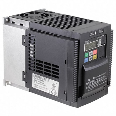
 Figure 1: VFDs, like the 3G3MX2-A2015-V1, are indispensable for a wide variety of process and discrete-automation applications — providing tight control, safety, and top efficiency to electric-motor-driven axes. One caveat is that VFD operation naturally generates EMI that can (if left unaddressed) degrade the communications of nearby controls and feedback; damage adjacent mechanical components; and spur various nuisance trips along with other suboptimal system behavior. (Image source: Omron Automation and Safety)
Consider how VFDs work for insight into why they can in suboptimal designs and cause problems in the very motors they drive as well as other nearby equipment. In short, VFDs:
- Accept as input the sinusoidal current of ac utility power and then
- Rectify (convert) line power into direct current
- Use insulated gate bipolar transistors (IGBTs) to invert (change back to ac) the dc current — more specifically, into precisely modulated pulse trains
Basically, the drive switches turn voltage off and on for chopped current that prompts the motor to turn as if receiving smoothly modulated sine wave of current. Under this form of driving — called pulse-width modulation or PWM — output speed is ultimately dependent on the frequency of the current pulses.
VFDs of yore that executed this process via silicon-controlled rectifiers (SCRs) or bipolar junction transistors (BJTs) were slower switchers than today’s IGBT-based VFDs. It’s the higher frequency of IGBT switching that allows quick and precise motor control … but it’s also what can cause problems in the form of both conducted and radiated electromagnetic interference (EMI) and radio-frequency interference (RFI).
VFD noise effects on the motor, controls, and the drive itself
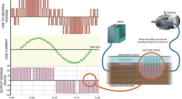
EMI issues arise because even when the drive is powering a motor to run at low speed, the way in which each electrical pulse is a square wave with bus-voltage amplitude means the power sent to the motor includes rather dramatic dV/dt voltage rise times — expressed in μsec or fractions of μsec.
Just consider one such issue — that of reflected waves of voltage. Upon startup, the electric motor’s stator windings behave as an inductor that gradually builds a magnetic field and then passes current. The cable feeding electrical power from the VFD to the motor sees an impedance mismatch at its motor junction. Here the aforementioned overshoots cause reflective waves to bounce some of the voltage waveform’s leading edges back into the cable (toward drive electronics) at the cable’s high-impedance connection with the motor.
Reflected waves of voltage arise from voltage overshoots caused by the dramatic dV/dt of PWM.
A factor that can worsen this phenomenon is excessively (or in some cases unavoidably) long cable runs from drive to motor. Long cables have high inductance and impart more opportunities for voltage spikes along with the compounding of reflected waves than shorter cables. Compounded waves are particularly detrimental, as these waves (which have gone into phase) effectively form new waves having the sum of the originals’ voltage and current.
 Figure 2: The square waveform of VFDs electrical pulses at bus-voltage amplitude causes dramatic dV/dt voltage rise times that (if not addressed) can, in turn, create various electromagnetic problems. (Image source: Design World)
Note motors (just like VFDs) can also sustain damage from reflected waves and voltage spikes. That’s why many of today’s automated installations include inverter-duty motors. These motors have stator windings featuring high-performance insulation and other elements to boost overall thermal capacity and (in most cases) resilience when subject to voltage spikes. Ratings are organized by surge-voltage magnitude and duration — with higher ratings for designs involving longer (less sudden) rise times. Of course, motors not built to inverter-duty specifications can accept driving by a VFD. However, application of these less robust motors should generally be limited to automated equipment with moderately challenging parameters. Any such motors driven by a VFD may also require a short cable run as well as inclusion of line reactors and other protective components.
Cables to the rescue: specially designed for VFDs
Besides threatening the VFD, in-phase compound waves with sufficiently high voltage can damage inappropriately utilized general-purpose cable. More specifically, the high-voltage spikes associated with VFD operation can stress, heat, and even pierce the cable insulation. To prevent this issue, cable specifically designed for use with VFDs includes:
- Heavy-gage (small-AWG) conductors rated to carry all anticipated peak voltages
- Sufficiently thick interfaces and insulation of specially engineered cross-linked polyethylene or (in some cases less preferred) polyvinyl chloride
- Sheaths and other elements to disperse and ground VFD-generated spikes and noise
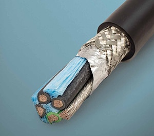
 Figure 3: Alpha Wire's cables for VFDs include cross-linked polyethylene insulation for electromagnetic corona resistance, low capacitance (even over longer cable runs), and good low-temperature performance. (Image source: Alpha Wire)
One quantifiable measure of a cable’s resistance to reflective waves is its corona-inception voltage — often measured in kV. Recall from basic physics instruction that corona (so-called for its crown of faint glow) is a sudden ionization of air surrounding a highly localized voltage. This ionization can (if not prevented with sufficient insulation around the conductor) generate ozone and various nitrous compounds that can quickly destroy inappropriately applied cable. That’s why thickly insulated VFD-rated cable should be used — cable meeting or exceeding the construction requirements indicated by VFD suppliers and far exceeding the National Electric Code (NEC) standards for general-purpose thermoplastic high-heat nylon-coated (THHN) wire. Where VFDs operate outdoors or in other wet locations, engineered polyethylene insulations may be most appropriate. Refer to the Digi-Key article The Right Cable for an Industrial Application for more information on other phenomena that affect VFD-driven designs and their cables — including inrush currents as well as common-mode currents.
VFD cabling best practices
Besides keeping VFD cable runs to a minimum — to shorter than 50 ft if possible — it’s also necessary to properly ground all parts of a motor-driven piece of equipment … including control and machine panels. This means using a common ground block or master-potential arrangement that prevents the detrimental effects of ground loops arising from voltage potentials between various machine points to ground. That’s especially true where machinery feedback relies on voltage reference values that (if not protected from inadvertent currents through ground) could report false values. This topic is detailed more fully in the Digi-Key article Measure Small Signals Riding on High Voltages and Avoid Sensor Ground Loops.
In fact, many designs will also require the addition of subcomponents such as filters, cable-side ferrite rings, motor-shaft grounding rings, and shields to fully address EMI. Case in point: A simple complementary part that’s often indispensable on VFD installations is called a grounding strap. This flat part consists of a braided strip of tinned copper with a ring terminal at each end. When integrated into a motor-driven design, grounding straps connect the drive’s protective-earth terminal (included on all VFDs) to ground … and drain high-frequency electrical noise to ground far better than round grounding wire. Its relatively high amount of surface area accommodates the way ac power (especially at high frequencies) tends to flow at a conductor’s surfaces or skin — hence the term skin effect to refer to this behavior.
 Figure 4: This tinned-copper ground strap is corrosion-resistant, flexible, and RoHS compliant. Such straps are useful in grounding portions of VFD installations, as they accommodate the way high-frequency noise tends to travel at conductor surfaces. (Image source: Falconer Electronics)
Another caveat here, though: Besides protecting against conducted EMI, designs should also protect against capacitively coupled noise transmitted at high frequencies. That includes noise that can enter the VFD-motor circuit through elements such as grounding straps as well as unshielded motor cables in metal conduit … both of which readily conduct EMI and generate ground loops. Another area where capacitively coupled noise must be mitigated is between the VFD-driven motor windings and frame to ground.
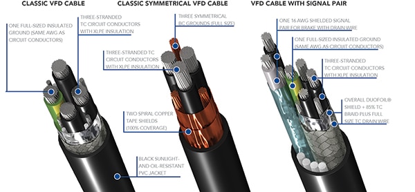
 Figure 5: Shown here is a chart from an educational PDF downloadable at digikey.com that compares the construction of three VFD-appropriate industrial cable designs. (Image source: Belden Inc.)
Conclusion
VFDs abound in process-type applications in HVAC, oil and gas, and general pump, compressor, and boiler operations. VFDs are also essential in an array of discrete industrial-automation systems employing electric motors to run moving axes on conveyors, mills, elevators, and other equipment that may benefit from efficiency increases.
The successful application of these drives depends on the consideration of their potentially harmful electrical and electronic effects on connected and adjacent components and systems … and in fact, the use of VFDs usually necessitates the inclusion of specialized electrical filters, terminations, grounding systems, and VFD-specific cable.

Disclaimer: The opinions, beliefs, and viewpoints expressed by the various authors and/or forum participants on this website do not necessarily reflect the opinions, beliefs, and viewpoints of DigiKey or official policies of DigiKey.


