製造商零件編號 BH-25C-1
BATTERY HOLDER COIN 20MM PC PIN
Adam Tech
Battery Holders Batteries Switches Pushbutton Microcontrollers LEDs / Discrete / Modules Resistors
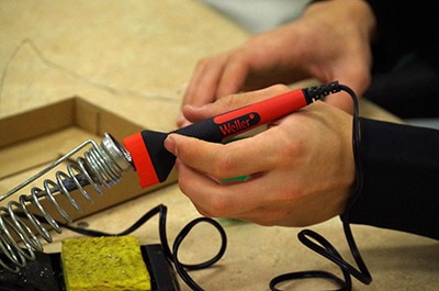
Whether you’re a seasoned hardware hacker or just getting into soldering, the 2025 Open Sauce badge is a fun, blinky reminder of what makes this community awesome: hands-on experimentation, creative engineering, and sharing cool projects. This guide walks you through assembling your badge from start to finish—no guesswork, just glowing results. Ready your soldering iron, check your kit, and let’s bring this badge to life.
![]()
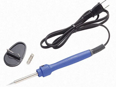
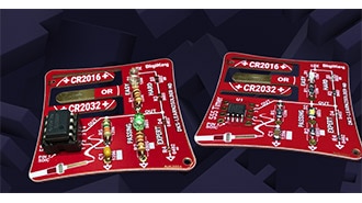
Begin by examining your kit. You should have:
![]()
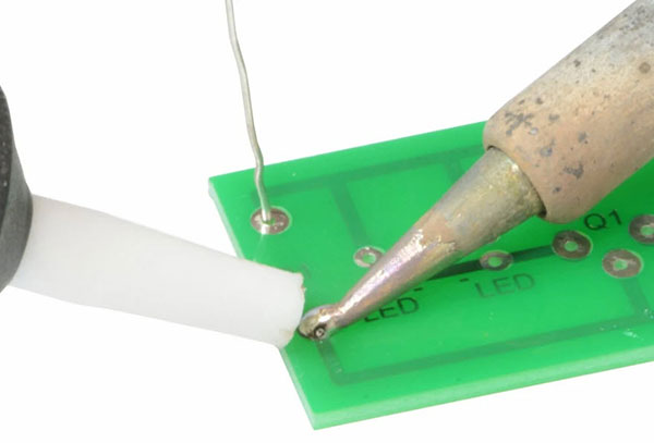
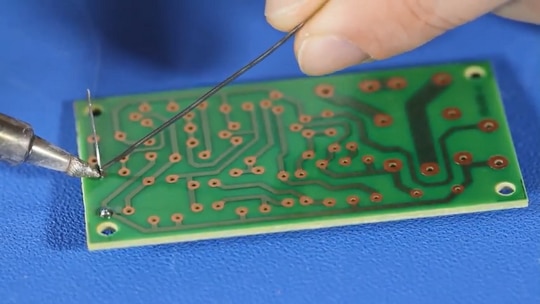
Turn your badge over and locate the spot for the battery holder.

Place the battery holder onto the badge, ensuring it matches the orientation shown.

While holding the battery holder in place, flip your badge over and locate the battery holder leads.

While ensuring the battery holder remains seated flat against the back of the badge, solder the leads into place. If this is your first time soldering, you can find helpful resources in the recommended content section above.


Next, insert the microcontroller IC on the back side of the badge. Align the small cutout on the IC with the cutout marked on the badge to ensure correct orientation.

Flip the badge while holding the IC in place, and solder one of the pins.

Double-check that the IC is still flat against the badge. If not, reheat the solder joint to seat it fully. Once the IC is fully seated to the badge, continue soldering the remaining pins.

Locate your resistor and bend the ends of the leads to fit the allotted space on the back of the badge.

Place the resistor into the designated holes – you may need to use a piece of tape or poster putty to hold it in place while you flip the board to solder the lead. Note: This resistor is used as a simple vibration sensor, so make sure you only solder the one lead and leave the other free to move within the cutout in the board.


With the single lead of the resistor soldered in place, cut off the excess.

Now that all the components on the back side are soldered, we can move to placing the components on the front side of the badge, starting with the switch.

Make sure you fully seat the switch to the board before soldering.

With the switch soldered, insert the first LED, making sure the long leg is placed through the hole with the oval solder pad, then bend the leads out slightly to hold it in place.

Repeat this for the four remaining LEDs.

Then solder and clip off the excess leads.

Finally, insert the IR photodiode into the PCB. Please note that the polarity listed on the badge is incorrect: You should insert the photodiode in the same orientation, ensuring the longer, positive lead is placed through the hole with the oval solder pad.

Solder and cut the excess leads for the photodiode, and now your badge assembly is complete.
Your 2025 Open Sauce badge is now fully assembled and ready to shine… literally! Just hold the button and shake the badge and you’ll see the familiar “OPENSAUCE” trail across the air in glowing POV style. If it’s not working as expected, don’t sweat it, double-check the unsoldered resistor is free to move in the badge slot to make and break contact as the badge is shaken, or try running it without the photodiode, as some attendees have reported better results without it.
Now that your badge is alive, show it off! Snap a photo or a POV video and share it on social media using #OpenSauce2025. And if you picked up any tricks along the way—or modified the badge to do something wild—share your build with the community in the comments below.
![]()
If you are having issues with soldered leads of the badge catching on your clothes, see last year’s badge guide here for tips on how to prevent this and other pro tips.
Note: if your badge isn’t spelling out OPENSAUCE, double-check that the unsoldered resistor lead is free to move in the slot in the badge. The shaking of the badge should cause the resistor to make and break contact with the sides of the slot, acting as a simple vibration sensor. Additionally, some users have reported that the badge POV function works better without the photodiode in the circuit.
P.S. If you need the code for this project, a user has located the GitHub repository for the firmware and shared it in the comments below. Additionally, if you do not have a programmer, check out the following tutorial for information on how to program an ATtiny MCU using an Arduino Uno.
How to Flash the Arduino Bootloader to an ATTiny85 IC