製造商零件編號 6354
CONSTANT CURR LED DRVR TPS61169
Adafruit Industries LLC
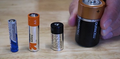
License: See Original Project 3D Printing Batteries LED Strips
Courtesy of Adafruit
Guide by Ruiz Brothers
Overview
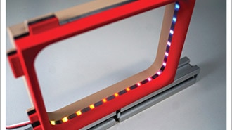
Print a case for the Adafruit TPS61169 Constant Current Boost Converter for LEDs!
The case has cutouts for the terminal blocks to attach LED nOOds, and cutouts for the current adjustment switches -- useful when powering multiple strips.
Tabs on the sides make it easy to mount to any prop, such as a sign or wearable.
The case snap fits together without the need for any additional hardware to mount the board inside the case.
Parts
1 x Translucent PLA
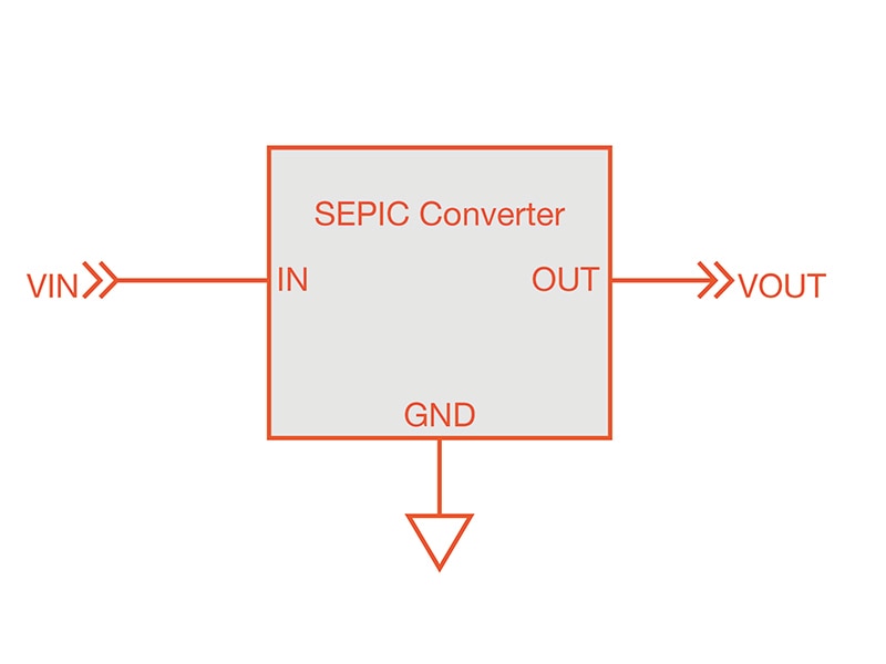
Circuit Diagram
The diagram provides a general visual reference for wiring of the components once you get to the Assembly page. This diagram was created using the software package Fritzing.
Adafruit Library for Fritzing
Adafruit uses the Adafruit's Fritzing parts library to create circuit diagrams for projects. You can download the library or just grab individual parts. Get the library and parts from GitHub - Adafruit Fritzing Parts.
The anode (+) end of a nOOd can be identified by a teeny-tiny hole or dot in the metal end tab.
3D Print
3D Printed Parts
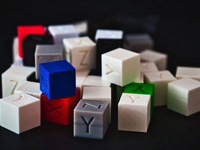
STL files for 3D printing will need to be oriented for printing using FDM machines.
Parts were printed with PLA filament.
The 3MF file is ready to print with colors assigned to print on multi color printers.
Original design source files may be downloaded using the links below.
The dropdown on the Fusion 360 site allows you to pick your preferred 3D file format like STEP, STL, etc.
Slice with settings for PLA material
The parts were sliced using BambuStudio using the slice settings below.
PLA filament 220c extruder
0.2 layer height
10% gyroid infill
200mm/s print speed
60c heated bed
Multi color print
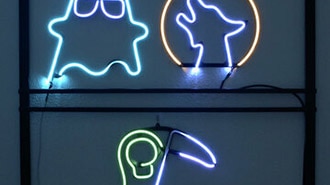
Letters on the sign have a .1mm indent on the front and back making it easy to "color" with the paint bucket tool. Use translucent filament to allow the light to diffuse.
Assemble
Measure wires
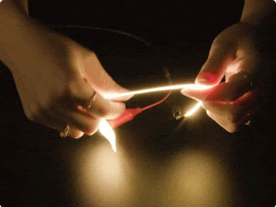
Use silicone wire to solder to the ends of the nOOds. Denote the positive and negative connections with markings or with red (+) and black (-) wires.
Use heat shrink tubing to protect the soldered ends. Slip a piece on before soldering and then slip it over the joint and heat to seal.
Use a flat head screwdriver on the terminal blocks to attach the wires into the + and - CC out connectors.
Measure and cut a JST socket wire for power and connect to the 3-5 Vin terminal blocks.
Assemble case
Note the + and - labels on the case to correctly align the terminal blocks on the board to place inside the case.
Align the lid part to the mini–DIP switches. Place one side of the lid over the snap fit part and then use force to snap fit the other side into place.
Use M2.5x5mm screws on the two tabs to mount the case.
Attach nOOds
The LED nOOds press fit into the channels on the sign part. Align the strip and gently press fit at the same angle so the filament strip does not twist along the channel.
Connect power and adjust the current to achieve to the desired brightness.