製造商零件編號 DFR0868
BEETLE ESP32-C3 VERSION 2
DFRobot
License: Attribution Arduino ESP32
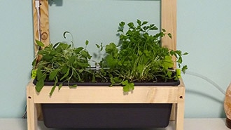
Recently, my wife has been working on setting up a garden, and as a tech enthusiast, I thought about how I could help her using technology. That's when I came across DFRobot's Beetle ESP32-C3. During my previous research, the ESP32 had already made it onto my shortlist of components, so this seemed like the perfect opportunity to give it a try.
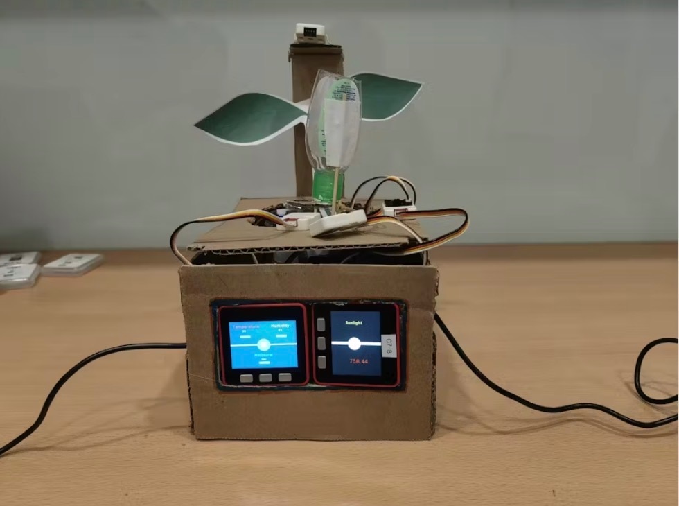
Using this small Beetle, I created a compact environmental monitoring terminal to collect data on temperature, humidity, light levels, and later, soil moisture. The data collected is displayed on a small screen and also sent to my server via MQTT. With this information, I can later implement features like automated irrigation.
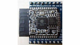
The Beetle ESP32-C3 is extremely compact, and when it arrived, I received two parts: the core board and an expansion board. The expansion board offers three sets of I2C interfaces, one serial port, and nine GPIOs. For such a small device, having so many interfaces is incredibly convenient for development. It even has an integrated lithium battery charging management chip, allowing for direct power supply from a lithium battery, perfectly covering the needs of my project.

HARDWARE LIST
1 GY-302 Ambient Light Sensor
1 AHT10 Temperature & Humidity Sensor
1 Capacitive Soil Moisture Sensor
You can also refer to the DFRobot alternative products below, which are functionally similar to the modules mentioned above, but the code in this post is not compatible with DFRobot's modules.
The following modules are DFRobot alternative modules:
- Analog Capacitive Soil Moisture Sensor
- Temperature & Humidity Sensor
I chose to use female headers on the expansion board to make adjustments easier and improve convenience during use.

I didn't use IO ports 3 and 10 on the expansion board, as their positions were a bit tricky, so I simply left them unsoldered.

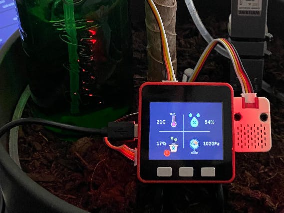
Final assembly result:

The programming part of this project was done using CircuitPython. I chose CircuitPython firstly because I wanted to learn a bit of Python on the way, but also because it was recommended by someone who said it was easy.
Here's a breakdown of the programming process:
1. Flashing the CircuitPython firmware:
CircuitPython is indeed simple to use, as it doesn't even require a complex development environment. The Beetle ESP32-C3 is officially supported, so flashing the firmware and writing code can all be done through a browser.
Firmware download and flashing instructions: DFRobot Beetle ESP32-C3 Download
Note: Before flashing, you need to pull IO9 low and short RST to put the ESP32 into download mode.

2. Writing the code:
CircuitPython typically recommends development boards with USB functionality, where, after flashing the firmware, you can simply upload code by placing it into the USB drive created by CircuitPython. However, the Beetle ESP32-C3 lacks USB functionality, so code and file uploads need to be done via the web.
After flashing the firmware, you will need to modify the Wi-Fi connection settings via CircuitPython's online installer (see the image below).

Once you've updated the Wi-Fi information, the board should reboot automatically, though for safety, you can manually short RST to restart it.
After rebooting, CircuitPython will connect to the Wi-Fi access point you set up and start the web service. You will need to check the router for the assigned IP address.

Using this IP address, you can access CircuitPython's web service, where you can upload, edit, run, and debug the code directly online.


Now, let's dive into the coding part:
CODE
import time

import board

import displayio

import wifi

import ssl

import rtc

import socketpool

import terminalio

import analogio

import adafruit_ahtx0

import adafruit_bh1750

import adafruit_minimqtt.adafruit_minimqtt as MQTT

import adafruit_ntp

from adafruit_display_text import label

from adafruit_st7735r import ST7735R

from adafruit_display_shapes.rect import Rect

from adafruit_display_shapes.line import Line

from adafruit_display_shapes.sparkline import Sparkline

# Create sensor object, communicating over the board's default I2C bus

i2c = board.I2C()  # uses board.SCL and board.SDA

tempSensor = adafruit_ahtx0.AHTx0(i2c)

luxSensor = adafruit_bh1750.BH1750(i2c)

loopCounter = 0

spi = board.SPI()

tft_cs = board.D7

tft_dc = board.D1

tft_rst = board.D2

displayio.release_displays()

display_bus = displayio.FourWire(spi, command=tft_dc, chip_select=tft_cs, reset=tft_rst)

display = ST7735R(display_bus, width=128, height=128, colstart=2, rowstart=1)

# Make the display context

def showSplash():

    splash = displayio.Group()

display.show(splash)

    color_bitmap = displayio.Bitmap(128, 128, 1)

    color_palette = displayio.Palette(1)

    color_palette[0] = 0xFF0000

    bg_sprite = displayio.TileGrid(color_bitmap, pixel_shader=color_palette, x=0, y=0)

    splash.append(bg_sprite)

    # Draw a smaller inner rectangle

    inner_bitmap = displayio.Bitmap(108, 108, 1)

    inner_palette = displayio.Palette(1)

    inner_palette[0] = 0xAA0088  # Purple

    inner_sprite = displayio.TileGrid(inner_bitmap, pixel_shader=inner_palette, x=10, y=10)

    splash.append(inner_sprite)

    # Draw a label

text = "Hello DFRobot!"

    text_area = label.Label(terminalio.FONT, text=text, color=0xFFFF00, x=20, y=64)

    splash.append(text_area)

# Make the display context

def initMainUI():

    view = displayio.Group()

display.show(view)

    # BG

    color_bitmap = displayio.Bitmap(128, 128, 1)

    color_palette = displayio.Palette(1)

    color_palette[0] = 0x7ecef4

    bg_sprite = displayio.TileGrid(color_bitmap, pixel_shader=color_palette, x=0, y=0)

    view.append(bg_sprite)

rect = Rect(4, 4, 120, 120, outline=0x666666)

    view.append(rect)

return view

showSplash()

time.sleep(1)

MQTT_HOST = "192.168.99.7"

MQTT_PORT = 1883

MQTT_USER = "gardener"

MQTT_PASSWORD = "53bffe07f84e0c5909ff569bb2a848e7"

MQTT_SUB_TOPIC = "/garden/notify"

MQTT_PUB_TOPIC = "/garden/notify"

# Define callback methods which are called when events occur

# pylint: disable=unused-argument, redefined-outer-name

def connected(client, userdata, flags, rc):

    # This function will be called when the client is connected

    # successfully to the broker.

print("Connected to Adafruit IO! Listening for topic changes on %s" % MQTT_SUB_TOPIC)

    # Subscribe to all changes on the onoff_feed.

    client.subscribe(MQTT_SUB_TOPIC)

def disconnected(client, userdata, rc):

    # This method is called when the client is disconnected

print("Disconnected from Adafruit IO!")

def message(client, topic, message):

    # This method is called when a topic the client is subscribed to

    # has a new message.

print("New message on topic {0}: {1}".format(topic, message))

# Create a socket pool

pool = socketpool.SocketPool(wifi.radio)

ssl_context = ssl.create_default_context()

# Set up a MiniMQTT Client

mqtt_client = MQTT.MQTT(

    broker=MQTT_HOST,

    port=MQTT_PORT,

    username=MQTT_USER,

    password=MQTT_PASSWORD,

    socket_pool=pool,

    ssl_context=ssl_context,

)

# Setup the callback methods above

mqtt_client.on_connect = connected

mqtt_client.on_disconnect = disconnected

mqtt_client.on_message = message

# Connect the client to the MQTT broker.

print("Connecting to MQTT ...")

mqtt_client.connect()

ntp = adafruit_ntp.NTP(pool, tz_offset=0, server="ntp1.aliyun.com", socket_timeout=5)

def updateTimeByNTP():

    r = rtc.RTC()

try:

        r.datetime = ntp.datetime

    except Exception as e:

print(f"NTP fetch time failed: {e}")

mainUi = initMainUI()

font = terminalio.FONT

labelIp = label.Label(font, text="255.255.255.255", color=0x333333, x=10, y=12)

labelTemp = label.Label(font, text="TEMP: 00.0C 100%", color=0x333333, x=10, y=24)

labelEarthHumi = label.Label(font, text="EARTH: 00000 3.3V", color=0x333333, x=10, y=36)

labelLight = label.Label(font, text="Light: 9999.99lux", color=0x333333, x=10, y=48)

line_color = 0xffffff

chart_width = 80

chart_height = 50

spkline = Sparkline(width=chart_width, height=chart_height, max_items=chart_width, x=38, y=60, color=line_color)

text_xoffset = -5

text_label1a = label.Label(

    font=font, text=str(spkline.y_top), color=line_color

)  # yTop label

text_label1a.anchor_point = (1, 0.5)  # set the anchorpoint at right-center

text_label1a.anchored_position = (

    spkline.x + text_xoffset,

    spkline.y,

)  # set the text anchored position to the upper right of the graph

text_label1b = label.Label(

    font=font, text=str(spkline.y_bottom), color=line_color

)  # yTop label

text_label1b.anchor_point = (1, 0.5)  # set the anchorpoint at right-center

text_label1b.anchored_position = (

    spkline.x + text_xoffset,

    spkline.y + chart_height,

)  # set the text anchored position to the upper right of the graph

bounding_rectangle = Rect(

    spkline.x, spkline.y, chart_width, chart_height, outline=line_color

)

mainUi.append(labelIp)

mainUi.append(labelTemp)

mainUi.append(labelEarthHumi)

mainUi.append(labelLight)

mainUi.append(spkline)

mainUi.append(text_label1a)

mainUi.append(text_label1b)

mainUi.append(bounding_rectangle)

total_ticks = 5

for i in range(total_ticks + 1):

    x_start = spkline.x - 2

    x_end = spkline.x

    y_both = int(round(spkline.y + (i * (chart_height) / (total_ticks))))

if y_both > spkline.y + chart_height - 1:

        y_both = spkline.y + chart_height - 1

    mainUi.append(Line(x_start, y_both, x_end, y_both, color=line_color))

display.show(mainUi)

adcPin = analogio.AnalogIn(board.A0)

while True:

    mqtt_client.loop()

if loopCounter > 86400:

        loopCounter = 1

if loopCounter % 120 == 0:

        updateTimeByNTP()

    clientId = wifi.radio.hostname

    ip = wifi.radio.ipv4_address

    now = time.time()

    json = f'{{"clientId": "{clientId}", "ip": "{ip}", "earthHumi": {adcPin.value}, "airTemp": {tempSensor.temperature}, "airHumi": {tempSensor.relative_humidity}, "time": {now} }}'

print(f"Time: {time.localtime()}")

print("Temperature: %0.1f C" % tempSensor.temperature)

print("Humidity: %0.1f %%" % tempSensor.relative_humidity)

print("Light: %.2f Lux" % luxSensor.lux)

print(f"ADC A0 vlaue: {adcPin.value} {adcPin.reference_voltage}V")

print(json)

    spkline.add_value(tempSensor.temperature)

    text_label1a.text = "%.1f" % max(spkline.values())

    text_label1b.text = "%.1f" % min(spkline.values())

    labelIp.text = f'IP: {ip}'

    labelTemp.text = "TEMP: %.1fC / %.1f%%" % (tempSensor.temperature, tempSensor.relative_humidity)

    labelEarthHumi.text = "EARTH: %d %.2fV" % (adcPin.value, adcPin.value / 65535 * adcPin.reference_voltage)

    labelLight.text = "Light: %.3f Lux" % luxSensor.lux

if loopCounter % 60 == 0:

        mqtt_client.publish(MQTT_PUB_TOPIC, json)

    loopCounter += 1

    time.sleep(1)