High-Voltage Differential Oscilloscope Probes: Why You Need Them
When it comes to taking measurements, modern power conversion devices using switching techniques require special handling, including the need for differential probes. This is because, unlike their analog predecessors, they don’t employ transformers to reduce the line voltage. Instead, they use the rectified line voltage as the DC bus source (Figure 1). This topology has interesting implications with respect to grounding and differential signals.
 Figure 1: Shown is a functional block diagram of a switched-mode power converter for full-wave rectification of the line voltage to generate a DC bus voltage. (Image source: Teledyne LeCroy)
In the configuration of Figure 1, the circuit full-wave rectifies the AC line. For a 120 rms AC line, the peak-to-peak voltage is 340 VAC. The full-wave-rectified voltage across the capacitor is 170 volts DC. A 240 volt line would double those numbers. This is used as the DC source for the switched-mode voltage regulator.
The power switches are configured in a half-bridge topology, with upper and lower switches alternately connected to the output. The voltage regulator (not shown) generates pulse width modulated (PWM) signals which regulate the output voltage by driving the gate-to-source voltage of the MOSFETs.
Why you need differential probes
Looking at Figure 1, there are some things to note. First, no point in the circuit is referenced to ground. The input line has a hot and a neutral wire. The neutral is ground referenced at its source and may be several volts off ground before reaching the powered device. The voltages in the power converter are essentially floating. Attempting to make a voltage measurement with an oscilloscope using a common passive probe requires connecting the oscilloscope ground somewhere. Connecting a ground lead to any point in this circuit could cause problems.
The second thing to note is that the upper MOSFET voltages are riding on the lower MOSFET’s drain voltage. This is switching between zero volts and the DC bus voltage. This presents another problem for a ground-referenced oscilloscope measurement.
The solution to this measurement problem is to use a differential probe.
Given the voltages encountered—up to 680 volts—it will have to be a high-voltage differential probe (Figure 2).
 Figure 2: Shown is the functional block diagram of a high-voltage differential probe which does not require a ground connection as it measures the voltage difference between the + and – probe inputs. (Image source: Art Pini)
A differential probe measures the difference between the inputs. High-voltage differential probes include attenuators and overload protection on each input. Typical attenuation values are in the range of 50:1 to 2000:1. This gives high-voltage differential probes an input voltage range from 1500 to 7000 volts.
The device being measured is modeled as a differential source consisting of two differential sources, a positive component (VP) and a negative component (VN), as well as a common-mode component (VCOM). The common-mode component is shared with both the + and – inputs. The + input sees VP + VCOM while the – input sees VCOM - VN. The probe, ideally, measures the difference between these input voltages or VP +VN, eliminating the VCOM term. Real-life differential probes attenuate the common-mode voltage but do not eliminate it completely. The differential probe’s common-mode rejection ratio (CMMR), the ratio of the attenuated common mode signal to its unattenuated amplitude expressed in decibels (dB), indicates the effectiveness of the differential probe. This figure of merit is frequency-dependent, generally falling with increasing frequency.
How to use a differential probe
Let’s look at using a high-voltage differential probe to measure the upper gate to source voltage in a 120 volt input, switched-mode power converter, similar to the one shown in Figure 1. The DC bus voltage will be about 170 volts. The gate-to-source of the upper MOSFET will ride on the switching signal of the lower MOSFET, a PWM signal switching between zero and 170 volts. The gate-to-source voltage will be on the order of 4 to 12 volts.
For this measurement, I recommend a Teledyne LeCroy HVD3106A-NOACC high-voltage differential probe. This 120 MHz bandwidth probe has a voltage rating of 1000 volts RMS. Its differential voltage rating is 1500 volts (DC plus peak AC), well matched to even a power converter operating off of 240 volts AC. It has an offset range of 1500 volts, making it easy to vertically expand the measured waveform to see details. The probe has a CMRR of 85 dB up to 60 Hertz (Hz) and 65 dB at 1 megahertz (MHz). This means that the 170 volt common-mode signals will be attenuated by better than 65 dB. The attenuated common-mode signal would have an amplitude of about 95 millivolts (mV). Since the gate-to-source voltage is on the order of 4 to 12 volts, the common-mode interference will have very little effect on the measurement.
For higher voltages such as those associated with 1500 volt DC solar photovoltaic (PV) inverter measurements, I’d recommend the HVD3206A. It has a maximum differential voltage rating of 2000 volts (DC plus peak AC) and has the same bandwidth and CMRR as the HVD3106A-NOACC probe.
Finally, for large three-phase machines and their controllers, the HVD3605A with its maximum voltage input of 7000 volts (DC plus peak AC), is the high-voltage differential probe I’d recommend. The high voltage range is the result of the 200:1 or 2000:1 attenuator available in this probe. It has a CMRR of 85 dB at 60 Hz, 70 dB at 10 kilohertz (kHz), and 64 dB at 1 MHz, and an offset range of 6000 volts.
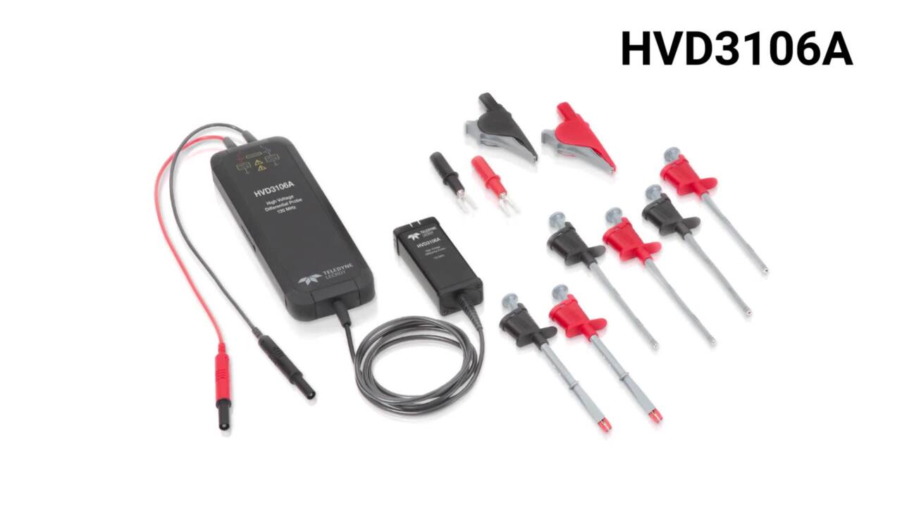
The HVD3000A series probes all have gain accuracies of 1% or better, are available with and without accessories, and with oscilloscope cable lead lengths of 2.25 and 6 meters (m) (Figure 3).
 Figure 3: Some of the high-voltage differential probe configurations for the HVD3000A series, which are offered with or without accessories and oscilloscope cable lengths up to 6 m. (Image source: Teledyne LeCroy)
Accessory kits vary with the model and include voltage-suitable clips or micro-grabbers.
Conclusion
High-voltage differential probes are useful in situations where there is no ground reference and where the signal to be measured is riding on top of another, high-voltage signal. For these situations, Teledyne LeCroy provides the HVD3000A series. All of these probes are well-matched to switched-mode power converter measurements requiring ground isolation. They are fully integrated into the Teledyne LeCroy oscilloscope operating system and are automatically sensed and scaled for accurate measurements.
關於作者

Arthur (Art) Pini 是 DigiKey 的特約撰稿人。他擁有紐約市立學院的電機工程學士學位,以及紐約市立大學的電機工程碩士學位。他在電子業有超過五十年以上的經驗,曾任職於 Teledyne LeCroy、Summation、Wavetek,以及 Nicolet Scientific 的重要工程和行銷職務。他對量測技術有所鑽研,並且在示波器、頻譜分析器、任意波形產生器、數位轉換器,以及電表方面有豐富的經驗。

Have questions or comments? Continue the conversation on TechForum, Digi-Key's online community and technical resource.
Visit TechForum