挑選固態繼電器時,工程師應考量哪些常見的設計參數?
資料提供者:DigiKey 北美編輯群
2025-10-08
多數工廠中,若固態繼電器 (SSR) 出現問題,往往是因為設計參數選擇不當所致。挑選 SSR 時需考量四個重要的設計參數,包括熱管理、切換類型的選擇、電流額定值的解讀,以及過壓保護。本文將深入探討這四個設計參數,並說明 Littelfuse 的 SSR 產品及其款式如何以最佳方式達到設計參數。本文在最後也會展示 Littelfuse 的 SSR 在測試中所表現出的優異耐久性。
適合不同負載應用的 SSR 切換類型
暖氣系統有時會產生意外的電磁干擾,導致無法通過合規測試。馬達控制應用有時會有反應時間較慢的情況。這兩個問題都源自一個相同的簡單原因。工程師在應用上挑選了錯誤的 SSR 切換類型。
不同類型的電氣負載需要不同的切換作法。加熱元件等電阻式負載,會在電流從零開始平穩流動時提供最佳表現。此作法可避免電壓暫態及電磁雜訊。
馬達等電感式負載則有所不同。無論 AC 波形的位置如何,馬達都需要迅速的切換反應。這是因為馬達中電流與電壓之間固有的相位關係,也是電感式電路的特性之一。
這些不同負載的電氣特性會產生完全不同的切換需求。使用錯誤的切換類型可能會導致工程師在系統中遭遇問題。圖 1 可說明零交越啟動與隨機啟動的現象,兩者分別適用於電阻式負載與電感式負載。
 for different switching modes") 圖 1:電壓波形可顯示不同切換模式下的導通時序 (綠色區域)。零交越切換可將暫態降至最低,而瞬間切換則可提供即時反應,適用於時間緊迫的應用。(圖片來源:Littelfuse)
圖 1:電壓波形可顯示不同切換模式下的導通時序 (綠色區域)。零交越切換可將暫態降至最低,而瞬間切換則可提供即時反應,適用於時間緊迫的應用。(圖片來源:Littelfuse)
這種不匹配會產生多重問題。電壓暫態會破壞敏感的電子元件,而電磁干擾因為會有合規性的問題,因此需要昂貴的重新設計。設備壽命會大幅縮短,因此無法預測系統效能。
大多數 SSR 製造商並未協助解決此問題。他們會提供通用的切換選項,但在應用上幾乎沒有提供指導。這意味著工程師必須自行解決複雜的負載相容性問題。因此最終要靠反覆試驗的作法來找出可行方案。這會延誤專案並增加成本。
Littelfuse 可提供適合應用的切換技術,並採用 IXYS 半導體與直接接合技術,專門針對負載特性而設計。像是 SRP1-CBAZH-050NW-N 和 SRP1-CRAZH-050TC-N 這類零交越切換型號,就可在 AC 電壓零交越時準確切換,藉此消除電氣暫態。這些型號非常適合用於控制最高 24 kW、600 VAC 的加熱系統,且電磁干擾極低。
 圖 2:由左至右為 Littelfuse 的 SRP1-CR、SRP1-CB 及 SRP1-CB…F SSR。(圖片來源:Littelfuse)
對於需要立即反應的馬達及電感式應用來說,包括 SRP1-CBARH-050NW-N 及 SRP1-CRARH-050TC-N 在內的瞬間切換型號,會在接收到控制訊號後立即啟動。可針對高功率的工業自動化因應高難度的馬達啟動特性。這種特定應用的工程作法可確保從最初安裝開始即具備可靠的效能。圖 2 顯示 Littelfuse SSR 的不同款式。
目前的評等準則與安全界限
即使遵循製造商的規格書,為何工程師仍經常挑選較小的 SSR?實驗室規範與實際運作條件之間具有落差。
電流額定值乍看之下似乎很簡單。但工程師之後就會發現問題。加熱元件在冷啟動時的電流消耗為標稱電流的 1.4 倍,且環境溫度可能超過 +40°C 的額定基準。此情境需要大量的降額處理。此外,線徑不足會進一步降低電流容量。這些因素會構成複雜的規格環境。過小的元件會提早失效。過大的單元則會浪費金錢和面板空間。
大多數 SSR 供應商都只提供基本電流額定值且應用環境的說明不足,因此會進一步加劇此問題。工程師就算取得規格書的數值,卻不瞭解操作的假設情況、安全界限或實際應用中的降額因素。此挑戰會迫使工程師透過成本高昂的試誤法進行判斷,不只會導致專案延誤,且常造成元件失效,但其實只要在一開始就正確依照指引,就可避免。
|
圖 3:Littelfuse 的 SSR 設計準則指出加熱應用的 20% 降額因素。功率值代表各項 SSR 額定值在標準 AC 電壓下的加熱器安全最大瓦數。(圖片來源:Littelfuse)
Littelfuse 透過明確的規格提供詳細的電流額定值準則 (圖 3),因此無需猜測。
- 10 A 的款式,如 SRP1-CRAZL-010TC-N,可安全處理 8 A 的加熱器電流,可促成 960 W 至 4.8 kW 不等的應用,同時可針對電氣環境提供整合式暫態電壓抑制器 (TVS) 防護。
- 25 A 的款式,例如 SRP1-CBAZL-025NW-N,可管理 20 A 負載,可支援 2.4 kW 至 12.0 kW 的系統,並具備加熱應用的零交越切換功能。
- 50 A 單元可控制 40 A 應用,能供電給 4.8 kW 至 24.0 kW 的設備。
每項規格都包含保守的 75-80% 利用率因數,以及詳細的溫度降額數據,可展現智慧的熱和電應力管理,藉此延長使用壽命。
防止電壓突波與電氣暫態
電氣暫態現象在工業環境中經常發生。此類情況包括電力線中的雷擊突波以及馬達切換操作期間的反電動勢產生。公用事業電網的干擾亦會產生超過 1200 V 的電壓尖峰。即使每次事件只持續數微秒,也可能會破壞 SSR 及與其連接的其他設備。隨著時間推移,多次小型暫態的累積性破壞就會導致零件毀損,最終造成生產停止。
在傳統作法上,需要外部突波保護裝置,因此會導致配電盤空間增加、佈線複雜,並且要謹慎協調各種不同的保護等級。許多 SSR 供應商的基本單元並不含整合式防護,迫使工程師必須設計獨立的突波抑制系統。但外部保護器會因為額外的連接而引進故障點,且礙於寄生電感和反應延遲,可能無法迅速反應。
, and anti-parallel thyristor output configuration for bidirectional AC switching") 圖 4:內部功能區塊顯示光耦合器隔離、觸發時序控制 (零交越或瞬間) 及雙向 AC 切換用的反向並聯閘流體輸出配置。(圖片來源:Littelfuse)
圖 4:內部功能區塊顯示光耦合器隔離、觸發時序控制 (零交越或瞬間) 及雙向 AC 切換用的反向並聯閘流體輸出配置。(圖片來源:Littelfuse)
Littelfuse 透過 SRP1-CR 系列提供整合式保護,並在 SSR 外殼內直接裝入 SMBJ 系列 TVS 二極體。圖 4 展示內部功能區塊,其中的光耦合器隔離與觸發時序控制,可促成此整合式保護方案。此元件級保護能在納秒內反應,將電壓尖波箝制在 900 至 1200 VPK 之間,以免受損。
像是暖氣系統用的 SRP1-CRAZH-050TC-N 以及馬達控制用的 SRP1-CRARH-050TC-N 型號,皆提供針對其特定應用最佳化的內建過壓保護。這些款式非常適用於配備變頻驅動器且常有反電動勢暫態威脅的電氣嚴苛環境。
整合式設計就無需外部元件,同時可在電路中精確配置所需的保護。相較於無保護的替代方案,此作法可展現增進的可靠性,並提供對電氣暫態的完整保護。
散熱與溫度控制解決方案
雖然大多數工程師都關注在電氣規格,但熱設計也會決定 SSR 的實際壽命。運作期間的發熱看似可控,一旦接面溫度超出安全限制就不是這麼回事了。半導體的退化一開始時無聲無息,但會導致效能不穩定。
挑戰都從小地方開始。大多數應用都在標準 +40°C 額定溫度基礎上運作,因此需要規格書上有敘述但並未強調的電流降額。再加上散熱膏塗抹不均、散熱片尺寸不足以及環境氣流不良,也會導致熱介面不一致。看似簡單的熱管理作業,實際上會變成複雜的工程挑戰,且具有顯著的成本影響。
Littelfuse 可透過 SRP1 系列提供整合式熱管理,並將熱控制的各個層面納入到完整的解決方案中。導熱墊已預先貼附,可排除安裝時的變數,同時可確保一致的熱傳遞,且無需使用髒亂的導熱膏。IXYS 半導體技術與直接接合技術,相較於標準元件,可提供更優異的散熱特性。提供詳盡的熱降額曲線,因此可針對各種工作條件精確挑選散熱片。
 (click to enlarge)") 圖 5:依據環境溫度及散熱片熱阻 (°C/W) 的負載電流限制。對於高溫工業應用來說,這是避免熱故障的關鍵考量。(圖片來源:Littelfuse)
圖 5:依據環境溫度及散熱片熱阻 (°C/W) 的負載電流限制。對於高溫工業應用來說,這是避免熱故障的關鍵考量。(圖片來源:Littelfuse)
圖 5 指出不同熱情境下負載電流與環境溫度間的關係曲線。50 A 型號,如 SRP1-CBAZH-050NW-N 和 SRP1-CRAZH-050TC-N,可在最高 +50°C 下搭配適當的 0.7°C/W 散熱片,維持全電流容量。在 +40°C 環境溫度中搭配 1.5°C/W 散熱片,仍可提供 35 A 容量。因此非常適合在高溫工業環境中控制加熱器等應用。
測試結果與效能驗證資料
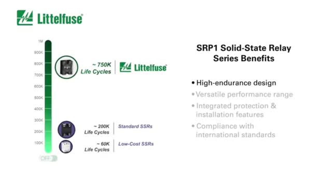
獨立的對比測試可驗證 Littelfuse 的效能聲明。在相同條件下,使用 2 倍額定電流進行 750,000 次循環的耐久測試時,Littelfuse 的 SRP1 系列表現明顯比三大競品更優秀 (圖 6)。Littelfuse 元件可完成整個測試循環,但競品分別在 200K、130K 及 60K 循環時失效。競品 3 更經歷災難性的半導體爆炸,具有安全風險。
") 圖 6:耐久性測試後 SSR 內部受損的視覺化對比,顯示頂蓋已拆除及詳細的故障模式。(圖片來源:Littelfuse)
圖 6:耐久性測試後 SSR 內部受損的視覺化對比,顯示頂蓋已拆除及詳細的故障模式。(圖片來源:Littelfuse)
故障後分析顯示出競品單元具有熱疲勞損壞,也展現 Littelfuse 的 IXYS 半導體技術、直接接合技術與熱管理可發揮效力。這項實際驗證可證明 Littelfuse 的整合式四大支柱作法能明顯提升可靠性。此結果能讓 SRP1 系列成為關鍵工業應用的明確首選,同時符合 cЯUus、CE 及 RoHS 法規標準。
結論
Littelfuse 的 SRP1 系列 SSR 能克服引發工業 SSR 故障的四大工程挑戰。採用與應用匹配的切換類型以消除電磁干擾,並具有保守的安全界限,以避免尺寸較小引起的故障。整合式過壓保護可處理電氣暫態,並具有先進的熱管理技術可延長使用壽命。實際測試證明具有卓越效能,可達到 750,000 次循環,反之,競品則在 200,000 次循環或更少下就發生故障。此工程作法可確保從安裝到多年的嚴苛工業應用期間均達到可靠的運作。
聲明:各作者及/或論壇參與者於本網站所發表之意見、理念和觀點,概不反映 DigiKey 的意見、理念和觀點,亦非 DigiKey 的正式原則。