Take control: How NXP's Patent-Pending SCT Improves Motor Control
資料提供者:Convergence Promotions LLC
2011-10-26
Electric motors are everywhere these days, driving motion in everything from washing machines and exercise treadmills to the heating and cooling systems in commercial buildings. Unfortunately, all those motors consume quite a bit of energy. Some experts estimate that roughly 60 percent of all the electrical power generated in the U.S. is consumed by electric motors. One way that designers can reduce power consumption is by moving to newer motor technologies, such as brushless DC and AC motors.
Compared to their brushed counterparts, brushless motors are more reliable, quieter, produce fewer electromagnetic emissions, and are safer because they eliminate the sparks associated with the brush and its commutator. They're also more efficient, which means they use less energy. On the other hand, brushless motors also require more complex electronics to manage their operation, and designing that circuitry can increase development time and drive up the total system cost.
As a long-time supplier for industrial applications and white goods, NXP Semiconductors is very familiar with the issues associated with motor control. Design challenges include finding ways to improve accuracy, increase speed, reduce power consumption, limit electromagnetic interference (EMI), lower cost, and expand the number of tasks the system can perform. To meet these challenges, our 32-bit ARM Cortex-M3 and Cortex-M4 microcontrollers (MCUs) include dedicated peripherals for motor control. The state-configurable timer (SCT) is a unique, patent-pending peripheral that gives designers a new level of programmability for motor-control operations.
State-configurable timer (SCT)
The SCT is a sophisticated yet easy-to-configure timing function that delivers unprecedented flexibility. It lets designers configure advanced timing operations--including those required for complex motor-control functions -- while meeting tight development schedules. From an architecture standpoint, it is a timer-capture unit coupled with a highly flexible, event driven state machine. It brings two familiar concepts, event and state, to the area of timing, and thus enables wide variety of operations, including timing, counting, output modulation, and input capture.
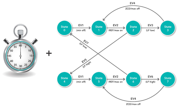
Table 1 introduces the five basic building blocks of the SCT: the timer, events, states, inputs, and outputs.
| Block | Supports | Description |
| Timer | Up or up/down counting | Two 16-bit counters or one 32-bit counter, with up or up/down counter functionality and clocked by the bus clock or a selected input. |
| Events | Up to 16 | Transitions that happen when a predefined condition occurs (counter status, output generation, state change, etc.). |
| States | Up to 32 | Conditions that define the context in which defined events are evaluated. |
| Inputs | Up to 8 | Signals evaluated by the SCT. They can contribute to the generation of events. |
| Outputs | Up to 16 | Signals generated by the SCT. They can contribute to the generation of events. |
Events can be programmed to be active (that is, to perform actions) upon verification of programmable conditions based on timed matches, I/O signals, or a combination of the two. Events are defined in the SCT control register. Each hardware event can be configured to drive an output signal, trigger an interrupt request (IRQ), perform a DMA transfer, or influence the behavior of the timer itself (by stopping, starting, resetting, or suspending the timer).
Dedicated shadow registers, which hold the counter match value, are used to define a time-based event or the time-based portion of a combined time- and I/O-based event. The content of the shadow registers can be changed by the application at runtime to modify the match point. The new value is loaded into the register when the associated timer reaches its limit (when reset to zero in up-counting mode, or when the timer reverses its direction in up/down-counting mode). This portion of the SCT is, in essence, an advanced timer.
Adding the concept of states gives the SCT the ability to provide more complex sequencing. Every timer is associated with a state machine via a state register. Events can be programmed to trigger a jump in the state machine, from one state to another, during operation. The user-defined states can also be configured to filter a specific subset of all possible pre-defined SCT events. In other words, events can be made active only during specific states. The designer can associate the behavior of the SCT with a state-machine algorithm, and thus make the system react differently to certain events depending on the SCT's current state. This ability to define a more complex sequence of events makes the SCT more sophisticated than a classical timer or PWM-generation block. It lets the SCT evolve autonomously over time, through the state machine, in response to time-based or I/O-defined events. In the case of the Motor Control application, fewer CPU interventions are required since the SCT can handle most of the control sequence in hardware.
Another feature of the SCT is that it can be used to define events that evaluate the level or the edges of an input signal. Without the SCT, the designer would have to perform this task in software, by periodically polling the input line with the CPU in order to detect changes. Using the SCT to perform the task offloads the CPU and simplifies programming.
Similarly, defining an interrupt to detect a signal change on an input can introduce an excessive latency at the system level. The SCT provides an efficient way around this, by guaranteeing jitter-free response to an input signal, within one SCT clock cycle. In general, the SCT can be clocked at the same speed as the CPU (typically 150 MHz), with a resolution of up to 6.67 ns and a reaction time (to detect a signal change) of 13.3 ns.
The SCT-tool
As mentioned above, hardware registers are used to configure the states, events, and timer values. In the LPC1800 and LPC4300, this adds up to more than 290 registers. To simplify configuration, NXP has developed a toolset, based on a state-machine drawing tool, that allows the designer to configure the SCT in a graphical environment. The drawing tool, called the SCT-Tool, uses familiar bubbles and arrows as objects, representing states and transitions (Figure 2). Properties for the corresponding states and transitions are entered into an easy-to-use table (Figure 3). The SCT-Tool uses the table entries, along with assignments for the physical I/O and the timer values, to create all the required settings for the SCT. The SCT-Tool outputs the register settings in C code. There's no need for state-machine code, because the SCT's state-machine functionality is completely hard-wired.
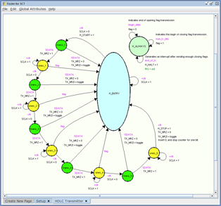
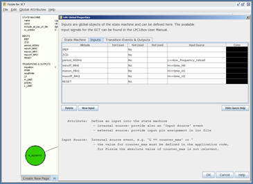
The SCT-Tool uses a simple, two-step design flow. Drawing the state diagram and specifying its properties is the first step, and assigning the I/Os and timers values in C is the second step. From there, the designer simply compiles the application framework for the LPC1800 or LPC4300 device, including the SCT components as part of the project. The SCT-Tool can easily be embedded into the standard workflow of various development tools, including KEIL µVision, IAR EWARM, or Code Red's Eclipse-based Red Suite. This makes it easy to test, debug, and revise SCT code as part of the larger application.
To help designers get up to speed quickly, the SCT-Tools include project examples for various types of applications. The examples provide insight into the principle of a state-machine design, and they can be used as the starting point for the designer's own ideas. The SCT-Tool, along with informative training videos, can be downloaded from NXP's website.
A sample configuration: FOC algorithm
To demonstrate the use of the SCT, we designed a sample application, using the LPC1850 Cortex-M3 MCU, to control a brushless AC (BLAC) motor. Our example BLAC motor has two main components: stator windings and a permanent magnet. It is a synchronous motor, which means the magnetic fields generated by the stator and the rotor have the same angular frequency. That means the motor doesn't slip the way an AC induction motor can.
For the control operations, we chose a field-oriented control (FOC) algorithm (also known as vector control) because it controls motor speed more efficiently that other approaches. The FOC algorithm also helps reduce motor size, cost, and power consumption. The basic operating theory of FOC is to measure and regulate the motor's magnetic field. Optimum leverage for the magnetic forces is achieved when the direction of the permanent magnetic field of the rotor is perpendicular, that is, at 90° angle to the induced magnetic field of the stator windings. This creates maximum achievable torque on the rotor axis.
Figure 4 gives a block diagram and the timing set-up of the FOC algorithm. The stator field is controlled by applying a voltage vector to the motor windings. This voltage vector is translated to six PWM signals, two for each motor phase. This translation is done by an algorithm called SVPWM. (For more on the FOC algorithm, please see NXP's application note AN10899).
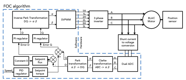

Figure 5 gives the hardware implementation of the FOC algorithm. All the required signals and connections can be implemented in hardware. The output signals are the six PWMs. The input signals consist of two current measurements, passed through in-phase shunt resistors, and one shunt measurement for the total motor current.
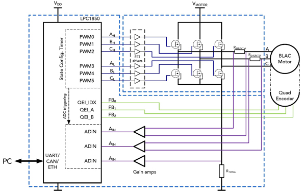
It's important to consider how the FOC algorithm will be implemented using the various peripherals on the MCU. For example, the FOC algorithm needs to measure the motor phase currents at an exact time. This requires very accurate but flexible ADC sampling. Having the right structure for triggering the ADC function makes it possible to sample the phase currents without additional signal filtering in software, and that can save significant CPU resources.
To support the FOC algorithm, we configured the SCT to implement four high-level features:
- Dedicated and independent activation/deactivation points for each of the six power lines (bridge phases)
Since the timer will be configured in an up-counting mode, the resulting PWM waveforms don't have to be symmetric with respect to the middle of the PWM period. This makes it possible to insert small time shifts (offsets) in the activation and deactivation point of each of the three phases. This in turn improves the accuracy of sampling currents over the shunt resistors. Additionally, if desired, the dead band time can be different on each pair of phases. - One activation (sampling) point for each of the ADC trigger signals
The algorithm needs to sample two current values, determined by measuring the voltage drop on two of the three shunt resistors placed on the motor current return windings (the third value is mathematically derived from the two measured values). - One dedicated interrupt trigger point
This is used to signal the application layer (the CPU) for a configuration change in the activation points (match registers), which are used to drive the motor phases and/or the ADC sampling points. - Eight output lines
Six output lines are used to deliver the generated PWM signals to the bridge drivers. Two additional output lines serve as ADC trigger signals, routed internally to the chip via on-chip multiplexers.
- 12 are used to define when each of the six PWM phases is activated or deactivated
- 2 trigger the ADC conversions
- 1 triggers a CPU interrupt
- 1 determines the PWM period length
The FOC algorithm doesn't really need us to define different states, since there are no external inputs which would determine a specific application state. So we have just an entry state (L_ENTRY), shown in Figure 6. At runtime, the application will change the match register values to modify the timing as appropriate.
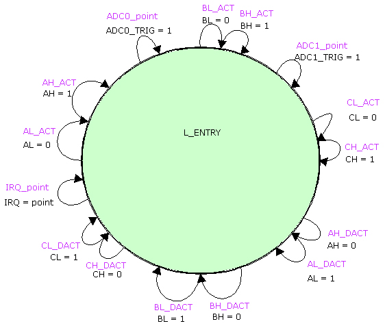
The six PWM output signals are AH, AL, BH, BL, CH, and CL. Each is controlled by a dedicated event that defines a separate activation (_ACT) and deactivation (_DEACT) point. The trigger points used for ADC conversion are represented by ADC0_TRIG and ADC1_TRIG. The event that generates the application interrupt is IRQ_point, and the event associated with each PWM period is Period_end. It clears the ADC trigger signals before the next PWM begins. Since there is no state change, all defined events loop back to the entry state.
Figure 7 shows a pseudo-state, called L_ALWAYS, that is not mapped to any physical state of the SCT. This is a graphical convenience, used to avoid specifying the same event for all states. This is especially useful when defining multiple states. The diagram indicates events that are always active, independent of the current state. (Since this application uses only one state, the L_ALWAYS diagram could have been included in the L_ENTRY diagram.)
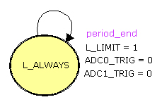
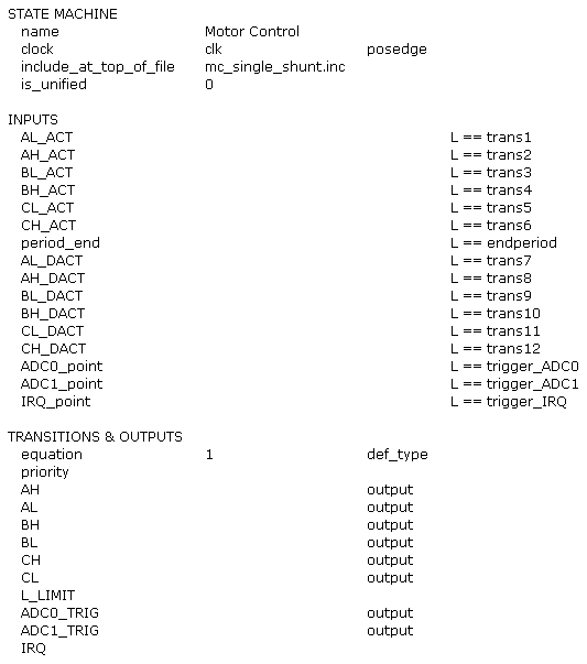
Table 2 lists the relevant settings for the state machine. All numerical values (trans1, trans2, trigger_ADC0, etc.), are user-chosen names that are defined in the application code. The SCT tool provides C macros to access the values.
LPCXpresso Motor Control Kit
To support fast time-to-market for motor-control applications, NXP offers the low-cost LPCXpresso Motor Control Kit, a universal development platform created in partnership with Embedded Artists. It is an ideal way to prototype a motor-control projects or simply explore motor-control functionality. It supports control of brushless DC (BLDC), brushless AC (BLAC), stepper, and dual-brushed DC motors.
The board has two full H-bridges, so up to four phases can be controlled with up to 100% duty cycle. Phase voltage, as well as in-phase current can be measured on three phases, and virtual ground voltage and common low-side current can be measured, too. For safety and protection, there is an input over-current trip protection. For design flexibility, there are several communications interfaces, including USB, Ethernet, CAN, RS-422/485, and a UART-to-USB bridge. The board also has a small graphic user interface (96x64 pixel OLED) with a joystick, to allow for simple, intuitive human interaction.
The board can be directly controlled by LPCXpresso LPC1114/LPC1343/LPC1768 target boards and future LPC1850/4350 Hitex boards. The kit includes an LPCXpresso Motor Control Board, an LPCXpresso LPC1114 target board with LPC-Link JTAG (supported by the LPCXpresso IDE), a BLDC motor with hall sensors, and a 24 V / 60 W power supply. The kit is available through NXP's distribution network.
Today's smaller, more efficient brushless motors require complex control electronics. The computational power provided by 32-bit MCUs is a good choice for developing these control functions, but there are still several design challenges to overcome. NXP's 32-bit ARM MCUs take these challenges head on, with dedicated motor-control peripherals that improve efficiency while simplifying design. Options include multi-channel PWMs specially designed for motor control, a QEI function, and, in particular, a new, patent-pending feature called the state-configurable timer (SCT).
The SCT combines a timer-counter with a state machine. It gives designers an unprecedented level of programmability for motor-control functions, including advanced FOC algorithms, yet is easy to configure using a straightforward graphical interface. The SCT is available on NXP's LPC1800 Cortex-M3 and LPC4300 Cortex-M4 devices. NXP also offers a low-cost LPCXpresso Motor Control Kit, developed in partnership with Embedded Artists, to help jump-start designs. To learn more, please visit http://www.nxp.com/products/microcontrollers-and-processors.

聲明:各作者及/或論壇參與者於本網站所發表之意見、理念和觀點,概不反映 DigiKey 的意見、理念和觀點,亦非 DigiKey 的正式原則。


