How to Quickly Add a Facial Recognition Camera to an MCU
資料提供者:DigiKey 北美編輯群
2018-07-12
Designers are being increasingly asked to add image and video analysis capabilities to current networks and new products, particularly for security applications. Facial and vehicle recognition is especially desirable and can add considerable value, but learning about and programming the details of facial recognition models for a microcontroller-based system can be time consuming and complex.
As is often the case, developers need to start experimenting and developing as soon as possible. This article will show how developers can save time by using an off-the-shelf combination of hardware and software to speed the incorporation of facial recognition into embedded systems.
Basics of facial recognition
Most developers are already familiar with face detection. This is the process of analyzing an image and determining where a face is present. Many smartphones have this capability. Facial recognition is the next stage after face detection. It is the process of analyzing a face and developing a mathematical model using data derived from relative distances of facial features. These include the distance between the eyes, and relative position of the eyes to the nose, jaw, ears, and cheekbones. The angle of the face with respect to the facial recognition camera is also determined, as it is important in determining the relative distances. Skin tone can also be detected and used for recognition.
That model is then compared to a database of stored mathematical models of known faces and an algorithm determines the best match. There is a probability (in percent) that the face detected matches a stored face. The alternative is that there is not a match, and therefore the face that is detected is unknown.
Facial recognition hardware
To incorporate facial recognition, designers have the option of pulling together the camera sensor, video and image front-end signal conditioning, GPU, control processor, memory and associated software and firmware. Of course, that takes time and can be a long learning curve. Alternatively, they can build a facial recognition system using off-the-shelf hardware and firmware. A good place to start is the B5T-007001 camera sensor from Omron Electronics, which is a turnkey solution of tested hardware and firmware (Figure 1).
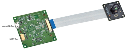
Figure 1: The Omron B5T-007001 facial recognition camera has all the functions required for a facial recognition application. (Image source: Omron)
The B5T-007001 has a USB 2.0 interface that can connect the camera board to a Windows® PC running Omron’s evaluation software. There is also a UART interface. Either the USB or UART interface can be used to connect the camera board to a host, either a microcontroller or a PC.
Both the USB and UART support a command API for configuring the camera. Omron’s on-board camera firmware analyzes the video and performs detection processing before sending it to the host.
Commands sent to the B5T-007001 from a host are executed sequentially. Once the host firmware sends a command to the camera, it must wait until the camera returns the result of that command back before sending another command. If the host detects a timeout, depending upon the application requirements, the host firmware can resend the command, or reset the camera by sending a RESET command.
Configuring the camera for facial recognition
Upon booting the B5T-007001, it must first be configured to operate in the physical environment in which it will be used. Commands are sent over the USB or UART interface and follow a set command structure (Table 1). The first byte of every command is always 0xFE, called the synchronous code.

Table 1: Command format for the B5T-007001. The LSB is on the left, MSB on the right. The LSB is transmitted first. During write commands, the data written to the B5T-007001 is in the Command Data field. (Image source: Omron)
The B5T-007001 supports 20 commands. For a full description of all commands, see Table 2.
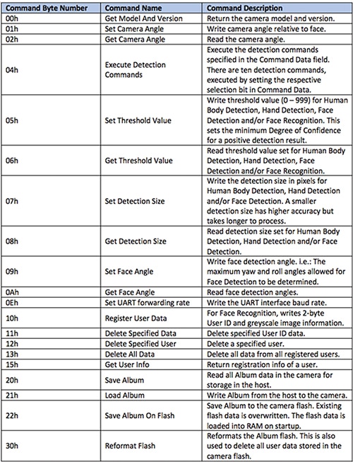
Table 2: Command list for the B5T-007001 with a short explanation of each command. Each command returns either a response code or error code. All writes are the host writing to the camera. All reads are the host reading data back from the camera. (Data source: Omron)
The camera is very flexible and is easily configured through a cable connected to the mini USB 2.0 port. Each person to be identified is called a User, and is identified by a 2-byte User ID. All User ID data is first written to the B5T-007001 by the host and includes a greyscale image of the user.
A collection of users is referred to as an Album. Up to 100 users in the Album are supported. The B5T-007001 stores all Album data, along with all other configuration data, in RAM on the camera board. During operation, the Album data stored in RAM is used for detection.
The camera does have flash memory on-board for Album backup storage. The command Save Album On Flash writes Album data for all users stored in RAM to the flash memory. The flash data is only loaded into camera RAM on camera startup. If during operation the Host firmware needs to reload the camera flash data into camera RAM, it would have to reset the B5T-007001 with a hardware cycling of power.
The Execute Detection Command (04h) is used to execute the various built-in detection algorithms based on the contents of the Command Data field. For each person detected in the camera’s field of vision, one or all of the following ten Detection Commands can be executed:
- Human Body Detection Command - Detects the upper half of human body, identified by the coordinates of the body center.
- Hand Detection Command - Detects open palm hands, identified by the coordinates of the hand center.
- Face Detection Command - Detects up to 100 faces, identified by an approximation of the center point coordinates.
- Face Direction Estimation Command - Estimates the direction of detected faces, presented as the yaw (left, right), pitch (down, up), and roll (counter-clockwise, clockwise) angles.
- Age Estimation Command - Estimates the age of detected faces from 0 to 75 years old.
- Gender Estimation Command - Estimates the gender of detected faces (male, female).
- Gaze Estimation Command - Estimates the eye gaze direction of detected faces, presented as yaw (left, right) and pitch (down, up).
- Blink Estimation Command - Estimates the blink degree of each eye of the detected faces, where 1 = eye is fully open and 1000 = fully shut.
- Expression Estimation Command - Estimates the emotional expression of detected faces, with results expressed as being neutral, happiness, surprise, anger, and sadness.
- Face Recognition Command - Recognizes detected faces compared to stored faces. The result returns the User ID of the face most likely to match the face being detected.
All locations are identified by [x,y] coordinates, where the upper-left corner of the image is [0,0]. For each result there is an associated degree of confidence from 0% to 100% expressed as a decimal number from 0 to 1000.
The camera supports an Image Output function, intended primarily as a debugging aid for the developer when setting up and aiming the camera. At 320 x 240 pixels, it is insufficient resolution for use as a security monitor. A second, high-resolution camera is recommended if streaming video is needed.
Before placing the camera in an application, it should first be configured in a development environment. The B5T-007001 comes with software that allows a PC to interface to it through a USB port. The PC software is also used with the B5T-007001 to identify and register users in the Album. As discussed earlier in the basics of facial recognition, the photos of user’s faces should clearly show the main features of nose, eyes, ears, and chin (Figure 2).
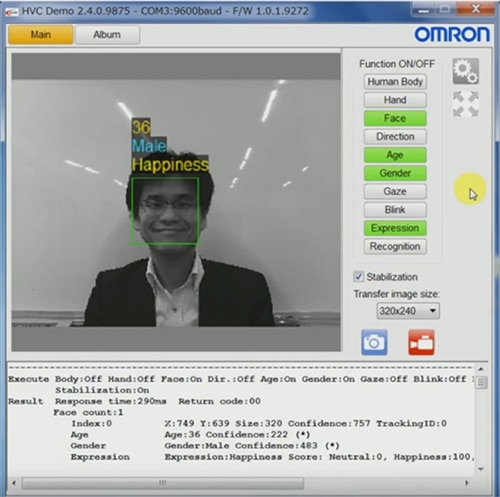
Figure 2: The PC user interface for the Omron B5T-007001 facial recognition camera is recommended for camera evaluation and development. It also serves as a user application for storing, changing, and deleting Album data. (Image source: Omron)
Adding facial recognition to a microcontroller system
The B5T-007001 can interface to a microcontroller with a USB or UART interface. The UART supports a maximum baud rate of 921600 bits/s, and the USB 2.0 interface supports 480 Mbits/s. Note that the camera does not support using both interfaces at the same time.
While the microcontroller needs to support basic I/O to be useful with the B5T-007001, more advanced development might require image processing or the management of multiple cameras.
For such applications, the STM32F469 Arm® Cortex®-M4F microcontroller from STMicroelectronics supports four standard UARTs and has a USB 2.0 interface with on-board physical layer (PHY) to save board space and component count (Figure 3). The microcontroller also has an on-chip MIPI® Alliance D-PHY to support MIPI® CSI-2 and DSI-2.
For video processing, the STM32F469 Arm core runs at 180 MHz. It also supports hardware image processing through a separate Chrom-ART Accelerator™. This is a graphics accelerator which speeds up color transformations, while also performing fast block memory move operations. The STM32F469 has a 128-bit interface to the 2 Mbytes of flash with an instruction prefetch queue and a branch cache, allowing 0 wait states flash memory access at a 180 MHz CPU speed.
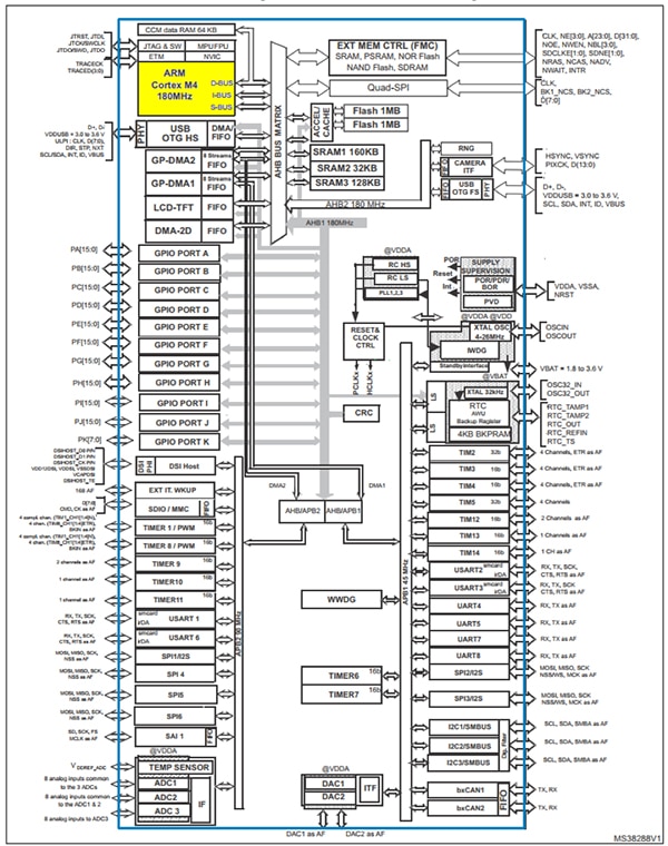
Figure 3: The STM32F469 microcontroller has two USB 2.0 ports and eight serial ports that can easily interface to the B5T-007001 and still have enough performance to support image processing. (Image source: STMicroelectronics)
The STM32F469 can interface to the B5T-007001 through one of the two USB 2.0 interfaces. The speed of the USB 2.0 interface is especially noticeable when reading and writing Album data between the STM32F469 host and the camera. With four UART interfaces, four USART interfaces, and two USB 2.0 ports, the STM32F469 can interface to up to ten B5T-007001s.
The STM32F469 also has an SDMMC external memory card interface (Figure 4). This works with a variety of flash cards such as commercial microSD and MMC cards and is useful for transporting Album data. For example, a B5T-007001 interfaced to a PC can be used to take photos of all users that need to be identified. The PC can then store the album data on a flash memory card, which can in turn be inserted into the STM32F469 single board computer (SBC) and used as updated Album data.
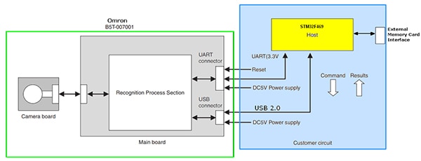
Figure 4: The STM32F469’s external memory card interface is useful for transporting data, such as updated Album data from a PC. (Image source: Omron)
Using the commands listed in Table 2, the STM32F469 and the B5T-007001 can be used as an autonomous security monitoring system. By executing the Face Recognition Command, the STM32F469 can identify known or unknown people in the camera’s capture area. Microcontroller firmware can compare the returned User IDs of identified people with an internal table of people stored in the microcontroller.
When known User IDs are matched, the STM32F469 can use any of its multiple peripherals to perform an action such as sound an alert or open a door. The microcontroller has an Ethernet port that can connect the device to a network, allowing it to send an email based on the User IDs matched.
The STM32F469 microcontroller also has an LCD TFT controller for controlling an external color LCD display. However, for additional video expansion, the MIPI® DSI-compliant interface can be used to connect to video cameras with a MIPI® multimedia interface. This can allow for later expansion by adding another camera for video streaming and additional processing. While this adds a much higher level of complexity, it can really expand the capabilities of a security system.
The microcontroller is supported by the STM32469I-EVAL evaluation board, which allows fast evaluation of all the microcontroller’s features. The evaluation board also has an LCD display which can be used to display video from the B5T-007001.
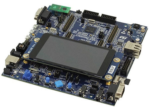
Figure 5: The STM32469I-EVAL is a complete evaluation kit for the STM32F469 microcontroller and can easily interface to the B5T-007001 using any of its USB, UART, or USART ports. (Image source: STMicroelectronics)
Conclusion
Off-the-shelf turnkey hardware has made it easier to add facial recognition to embedded systems projects by incorporating the needed algorithms in the camera board firmware. A simple command interface allows quick development of microcontroller firmware for interaction with the board without having to learn the details of image processing.

聲明:各作者及/或論壇參與者於本網站所發表之意見、理念和觀點,概不反映 DigiKey 的意見、理念和觀點,亦非 DigiKey 的正式原則。


