Industrial Automation and Control
目錄表
置頂
Controls and Programmable Logic Controllers (PLCs)
PLC structure
Environmental conditions
Connecting to the Network
Popular PLCs choices for small applications
Popular PLC choices for mid size applications
Popular PLC choices for large scale applications
Popular PLC content
Communication Protocols
Popular junction boxes for communications
Popular content for communications
Programming languages for PLCs
Ladder Diagram (LD) / Relay Logic / Ladder Logic
Function Block Diagram (FBD)
Sequential Function Chart (SFC)
Structured Text (ST)
Instruction List (IL)
CODESYS
Other Languages
Popular Programming Content
Movement and Actuators
Motor Control / Electrical motors
Solenoids / Relays / Contactors
Indicators / Alarms
Popular Actuator Content
Robotics
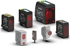
Industrial Sensors
Pressure
Photoelectric
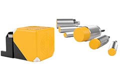
Proximity
Temperature
Distance
Rotational
Force and Load Cells
Popular Industrial Sensor Products
Popular Industrial Sensor Content
Safety
Regulatory Agencies
Safety Integrity Level (SIL)
Performance Level (PL)
Products
Popular Safety Devices
Popular Safety Content
Machine Vision
Barcode Readers
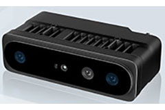
Machine Vision Cameras
2D vs 3D Vision
Popular Machine Vision Products
Popular Machine Vision Content
Conveyor Block Diagram
Circuit Protection and Line Filter
Uninterruptible Power Supply (UPS)
SMPS 24 VDC
Hold up / Buffer
PLC
IO Modules and Relays
Motor Control
Communications Block
Motor
Cameras and Sensors
Interconnect
Automation Resource Center
Industrial automation and control provides efficiency and consistency in factory operations. This is achieved by using controls to run the logic, industrial sensors to monitor the system, and actuators to move product. These systems need to be rugged and maintain high reliability.
Controls and Programmable Logic Controllers (PLCs)
Programmable Logic Controllers (PLCs) are industrial control units that monitor and respond to incoming signals. The signals they receive are based on sensor and process control data. PLCs respond based on algorithms that are programmed in them.
PLCs range in size from a small DIN rail mounted box to a full 19-inch electronic rack and cabinet with accessories and redundant power supplies.
As with all industrial equipment there may be local and national standards depending on where the equipment is deployed so be sure to double check any relevant standards that may apply.
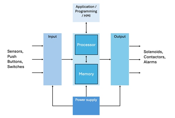
PLC structure
A PLC is a computing platform with external interfaces for inputs and outputs. Unlike a consumer PC (that may only have a few years of total run time and regular reboots) PLCs are purpose designed and built for industrial environments and applications where a 10 year of up time running 24 hours 7 days a week is considered the norm.
Structurally PLCs can be divided into a few broad sections:
- Input - sensor data and communication signals. Inputs can either be analog signals or digital signals.
- Output - process commands and communication signals (to other networked devices or electromechanical devices [such as relays, valves motor drives, or actuators]).
- Processor & Memory - evaluates incoming data and execute the program instructions.
- Power supply – provides the correct voltage, current, and power requirements, for the PLC.
- Application / Programming / Human Machine Interface (HMI) - HMI as the name suggests, allows humans to interact with the PLC easily to check conditions and operating status (of the PLC). As well, the HMI, can be used to update programing of the PLC. HMIs may range from a simple keyboard to a full touchscreen display.
 Programmable Logic Controllers or PLCs are the basic controller for industrial systems
Environmental conditions
Due to the industrial environments where PLC most often operate, they are constructed with higher standards then most consumer rated electronic devices. PLCs are required to be consistent and reliable. They are business critical devices. Any downtime with a PLC often results in a material impact to the business operating it.
Key features to endure these environmental conditions typically include:
- Circuit components with high operating temperature ratings (suited for -40°C to +85°C [-40°F to +185°F]).
- Conformal coatings on circuit boards to withstand high humidity and moisture content.
- Dust filters on all fan intakes or passive cooling heat sinks.
- Electrical isolation on I/O ports and surge protection in PLC circuity (to handle unexpected voltage spikes such as when industrial equipment powers up or down).
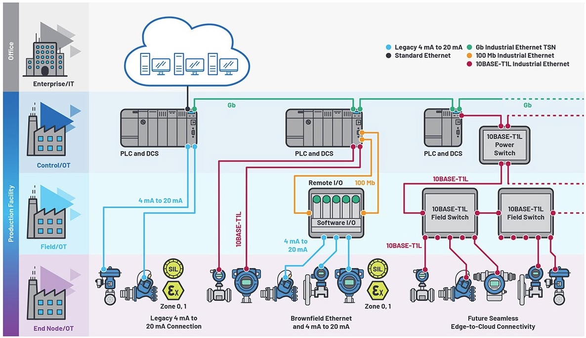
Connecting to the Network
PLCs often operate as a hub for communications within a factory, and more recently have become a conduit for information back to enterprise systems (residing in the cloud or back at headquarters).
 Sourced from:
 Popular PLCs choices for small applications
These controllers are ideal for a small setups (this includes operations like switching, timing, and basic sequencing). They are compact and cost effective without all the complexity of the more advanced controllers.


Popular PLC choices for mid size applications
These controllers offer higher I/O capacity, and advanced communication options. Can work for a small to medium applications. These can deliver strong performance without all the complexity.


Popular PLC choices for large scale applications
Built for demanding industrial environments, these can deliver top performance, and scale for large implementations. These often have more advance motion and process control, along with high-speed communication, and large I/O counts. These are most suitable for Industry 4.0 and robotics applications.


![]()
Modicon M221 Programmable Logic Controllers

Schneider Electric’s Modicon M221 programmable logic controllers have a variety of certifications offering tremendous versatility.
Popular PLC content

How to Construct a Siemens S7-1200 PLC Trainer
This guide shows you how to build a Siemens S7-1200 Gen 2 Safety PLC trainer (CPU 1212FC). The assembled kit, includes 24 VDC power distribution, user controls, and a motor starter along with a DigiKey-designed three-phase motor simulator.

How to Choose the Right-Sized PLC for Your Machine
This article provides pragmatic recommendations for selecting a PLC. It assumes the reader has some PLC knowledge but excludes advanced topics such as networking, IO-Link, and motion control.

Beyond Specs: Soft Requirements for Selecting the Right PLC
This article introduces critical Programmable Logic Controller (PLC) that are often overlooked. Instead of focusing on the hard specification we need to consider the soft (human) specifications such as consistent usage across the factory, software, workforce training, future modifications, and obsolescence.
Getting started with DigiKey’s Arduino Opta Kit
DigiKey’s Arduino Opta kit provides an excellent way to learn PLC programming and the fundamentals of industrial control and automation. This page identifies a series of labs designed to get you started.
PLC eMagazine
Programmable Logic Controllers (PLCs) have become indispensable in the world of industrial automation and control systems. Their robustness and versatility allow for complex operations to be managed with precision and reliability, catering extensively to the needs of engineers who require efficient, flexible solutions.
Communication Protocols
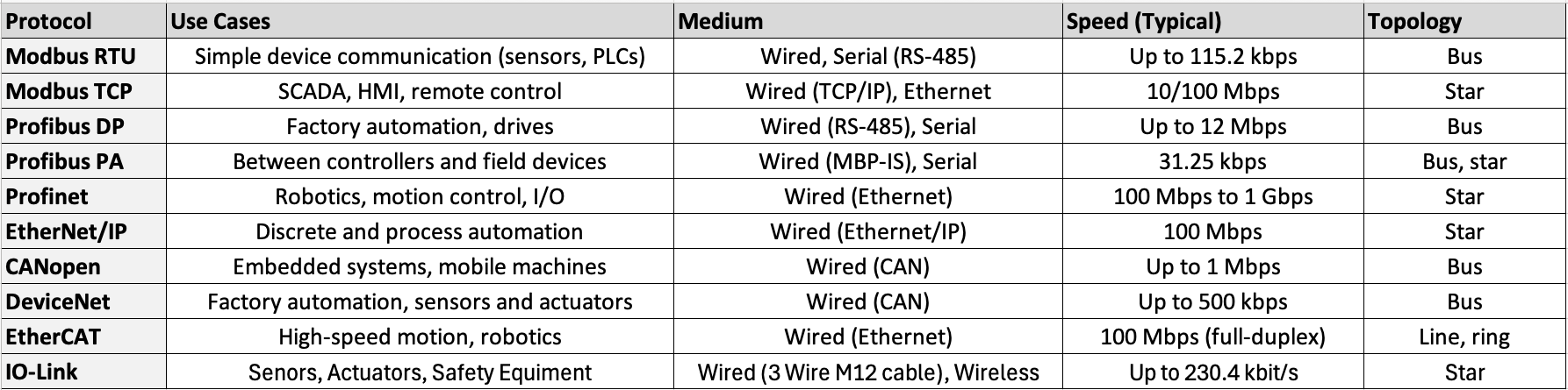 Comparison Table of Different Industrial Communication Protocols
Simple and widely used serial communication standard found in legacy industrial systems. Has limited transmission data rate (maximum of 115.2 kbits per second,) Modbus is popular because of its royalty free implantation and simplicity.
Modbus has two common variants:
- Modbus RTU (Remote Terminal Unit) - this is the most common version of Modbus and uses serial communication.
- Modbus TCP (also Modbus-TCP) - uses the Modbus RTU protocol with a TCP (Transmission Control Protocol) interface that runs on Ethernet.
PROFIBUS is short for Process Field Bus. It's a moderate data speed protocol for industrial automation. PROFIBUS uses a bus topology with controller devices and field sensors.
Despite the similar names PROFIBUS is not related to PROFINET. PROFIBUS is not based on ethernet and is generally an older protocol that is being phased out.
PROFIBUS has two variants:
- PROFIBUS DP (Decentralized Periphery) - is commonly used to communicate to industrial sensors and actuators and is commonly referred to as PROFIBUS (as this is the most frequently used variant.)
- PROFIBUS PA (Process Automation) – a variant tailored to operate in hazardous and explosive environments. In contrast to PROFIBUS DP, both data and power are transported over the same cabling.
PROFINET is short for Process Field Network. It's a scalable Industrial Ethernet protocol for collecting data and controling industrial equipment. It is based on ethernet, has support for real-time communication and deterministic data transfer, for synchronous control.
PROFIBUS and PROFINET are both IEC standards created by the same organization: PROFIBUS and PROFINET International (PI). Because of their common source, PROFIBUS and PROFINET do share some similarities. But they are very different with PROFIBUS being a serial-based communication and PROFINET being ethernet based.
CANopen is a higher layer CAN (Controller Area Network) based communication protocol for embedded device networks. It allows for off the shelf components and devices (from different manufacturers) to network together. CANopen was original designed for robotics and motion handling applications, but has also found widespread adoption in building automation, automotive, and medical devices as a common and easily implanted networking stack.
DeviceNet is an application layer protocol, that uses the CAN Bus physical and data link specifications along with the Communications and Information Protocol (CIP) which provides message information and object identification as an open standard supported by Open DeviceNet Vendors Association (ODVA.)
EtherCAT is an ethernet based fieldbus, for low latency and synchronization applications. Extremely fast, with synchronization times under 1 microsecond and deterministic real time communications. EtherCAT is ideal for motion control and high-performance automation, however the high hardware complexity and compatibility issues may be an issue for older hardware systems.
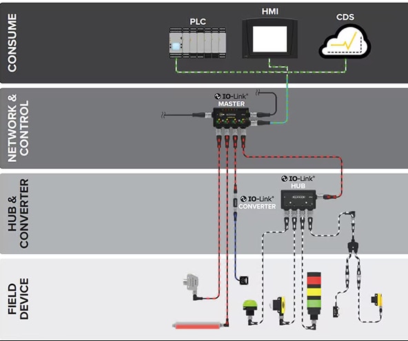 Source: Optimizing Industry 4.0 Communication Architectures using Multi-Protocol I/O Hubs and Converters
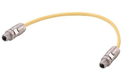
IO-Link is a short distance point to point digital communication standard used for Bi-directional communication with sensors and actuators. While IO-Link is not a field bus, the use of standard 24 VDC for power and unshielded M-12 connector 3 conductor cabling (as an agreed upon interface connector) makes IO-link an attractive alternative to many short run communication standards.
Popular junction boxes for communications


Popular content for communications

What is the difference between a Class A and a Class B IO-Link port?
This engineering brief is focused on the IO ports and the distinction between Class A and Class B. We will show that the class designation is concerned with power delivery to the field devices. We will also show that the design includes a measure of backwards compatibility.

M12 Port Hardware Myths: Common Misconceptions in Industrial IO-Link Setup
This engineering brief identifies recurring pain points when dealing with A-coded (5-pin) M12 devices and cabling.
Programming languages for PLCs
The International Electrotechnical Commission (IEC) standard 61131 section 3 outlines the five different PLC programing languages most common for programming PLC, we'll discuss them below.
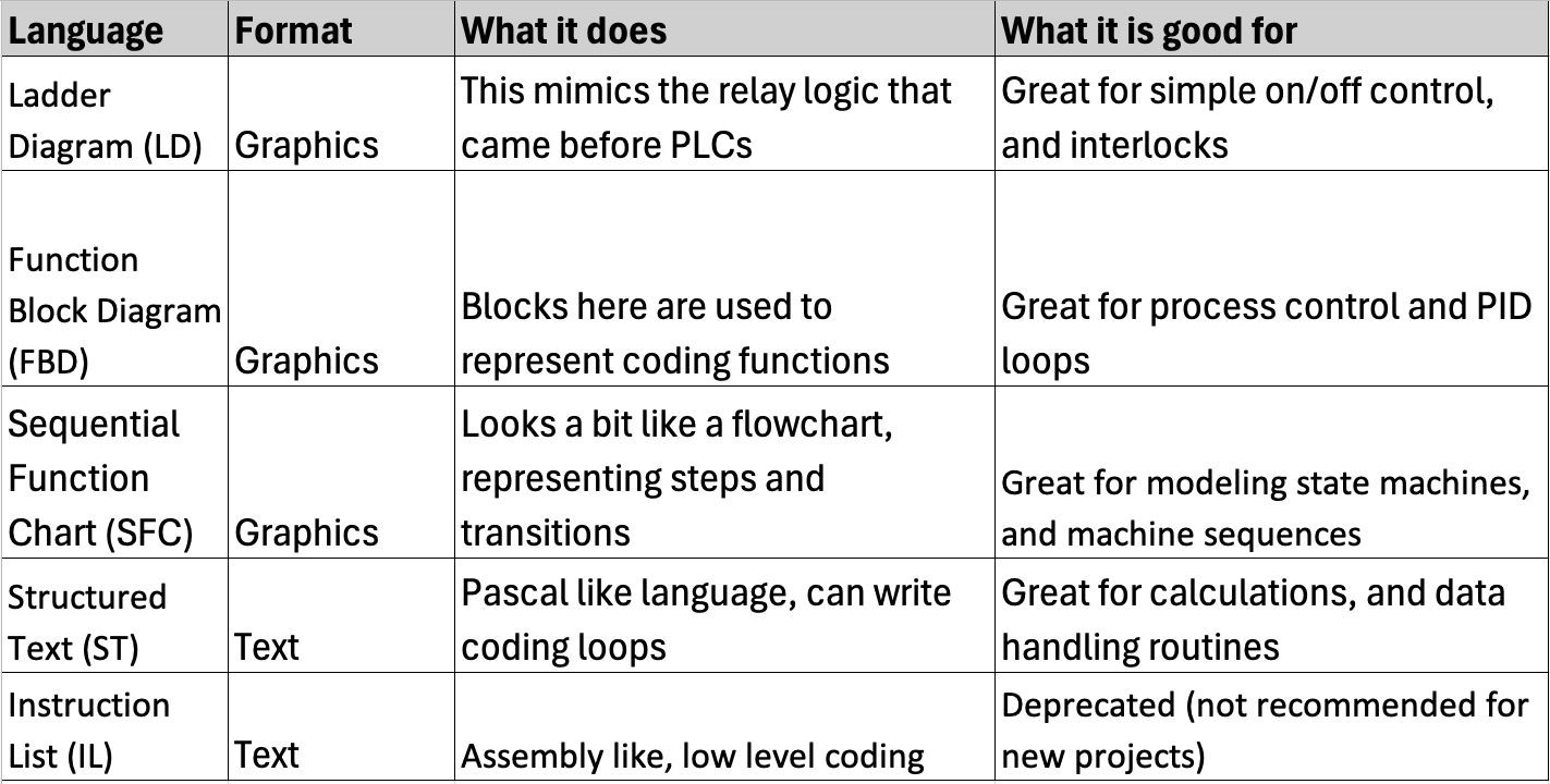 The 5 PLC programming languages standardized by IEC 61131-3 standard
Ladder Diagram (LD) / Relay Logic / Ladder Logic
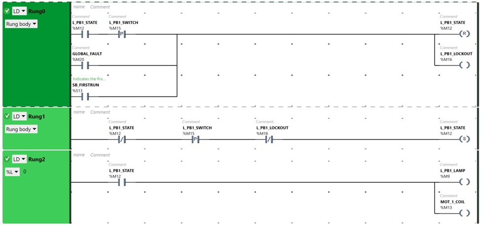 Picture from PLC Programming Language Introduction
Ladder Diagram, also known as Ladder Logic or Relay logic is a widely used graphical programming language that mimics the original relay logic and wiring diagrams that were used in process control before PLC devices were developed. Great for simple on/off interfaces, logic control, and safety interlocks, LD is still favored in modern PLC programming as it easy to get started with and logically consistent with each rung of the ladder detailing the input and control devices as read from top to bottom and left to right.
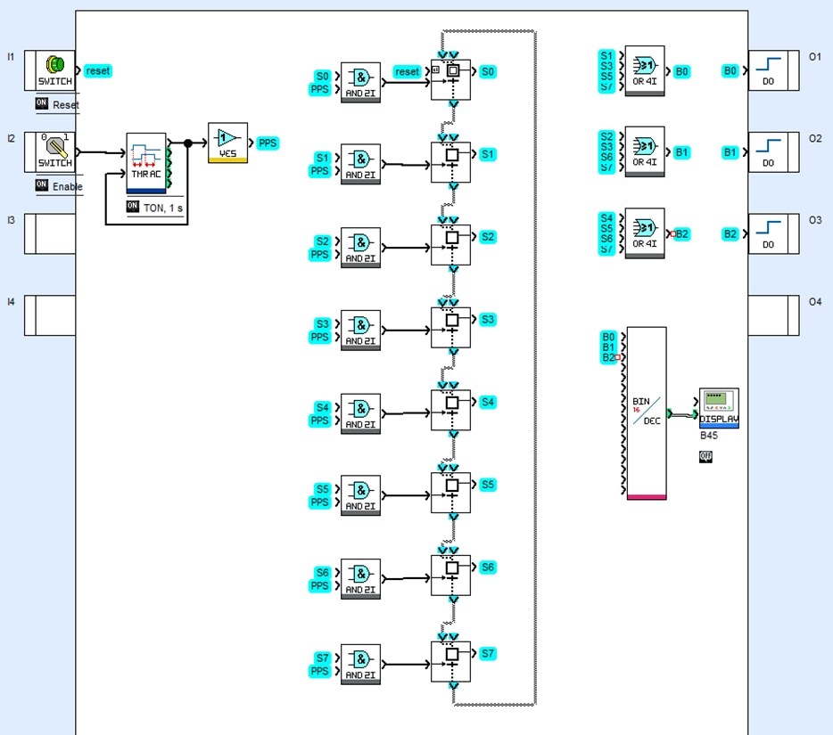
Function Block Diagram (FBD)
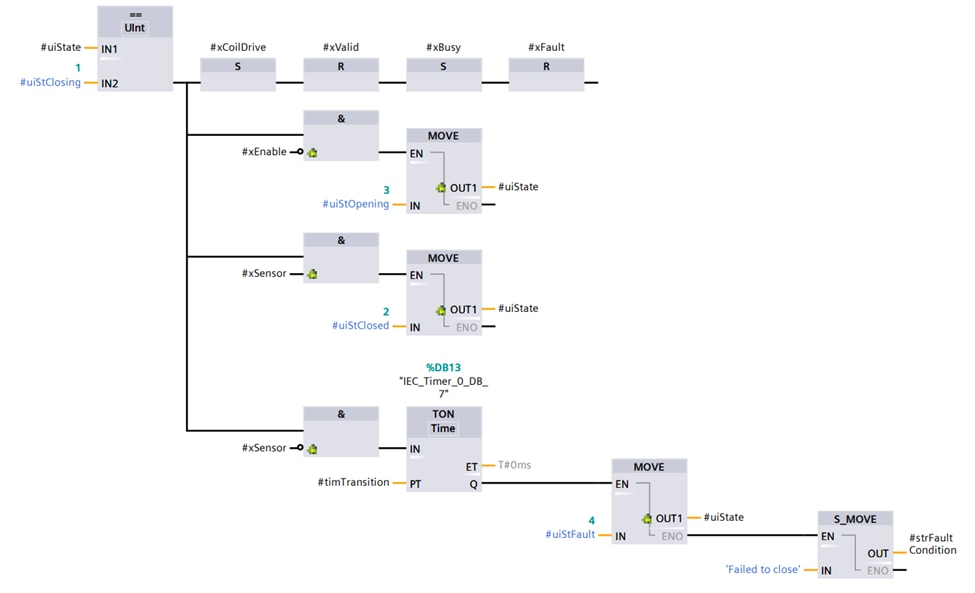 Picture from User-Defined Function Block (UDFB) in Function Block Diagram (FBD) Using Siemens TIA Portal
Function Block Diagram (FBD) is graphical programming language for PLCs that describes the functional relationship between input and output variables of the control process.
Each block used in the graphical diagram are used to represent different logical operations or coding functions. The left to right connections and flow lines between these blocks show the path data takes flowing between these functions. FBD is great for process control and PID loops as the function blocks and looping paths closely match.
Sequential Function Chart (SFC)
 Picture from
 Sequential Function Chart (SFC) is a graphical programming language used in PLCs useful for operations that have multiple states of operations or require state machine diagrams. SFC can look like a flowchart, with boxes representing steps (with actions required), transition functions (controlling the process flow between steps), and branch (if the process needs to operate in parallel sequence). SFC is great for modeling state machines, and machine sequences as the process can be modeled with logical control inputs and operations.
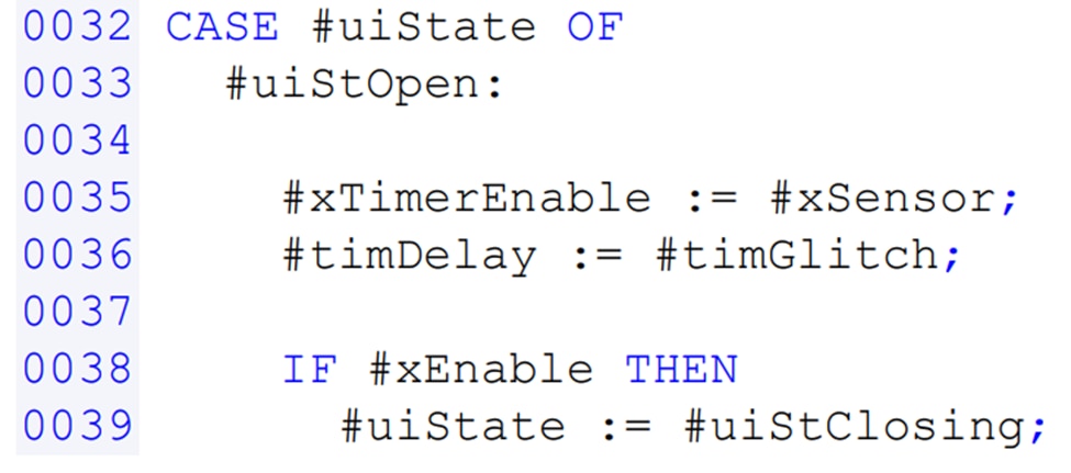
Structured Text (ST)
 Picture from
 Structured Text (ST) is a text-based programming language for programming PLCs that more closely resembles common computer programing languages such as C++ or Pascal. Due to ST's syntax structure and list of high-level programming statements, the implementation of coding loops, logical value calculations, and data handling routines is easily accomplished which makes it a good starting point for PLC programmers that have background in more traditional computer programming.
Instruction List (IL)
Instruction List (IL) is a text-based programming language for PLCs. A low-level coding language (IL) can be though to resemble Assembly programming language, with direct operating statements and data control actions.
As of the third edition of the IEC 61131-3 standard released in 2012, IL was deprecated and not recommended for new projects. Still available and supported by some PLC hardware due to the long support time of industrial PLC hardware. It is becoming phased out and being replaced by other more flexible programming languages.
CODESYS
Software development environment that is IEC 61131-3 compliant. It's accepted by multiple different PLC manufacturers and therefore allows a developer to have a development environment that is not solely based on a single manufacturer.
Other Languages
As PLC processing power increases, more programming languages are becoming commonly used for PLC programming (including C++ and Python). These flexible, modern languages are acting as the intermediate layer between the PLC and other applications such as networking with PCs and other workstations. That said, there are drawbacks to consider for real time control applications (for example, redundancy and life cycle upkeep costs) when using a non-IEC 61131-3 language.
Popular Programming Content

PLC Programming Language Introduction
The changes in processing power coupled with networking and powerful vision techniques allow, or perhaps demand, changes in programming languages.
PLC Ladder Logic FAQs: A Practical Path from Beginner to Mastery
This engineering brief provides answers to common questions regarding the use of ladder logic for Programmable Logic Controllers (PLCs) and smart relays.

Guide to Programming a PLC in C: Cycle Scan
Some modern PLCs may be programmed in C. Also, the line between the PLCs and PCs is blurred. Some hybrid PLCs like the Revolutions Pi are very flexible, allowing many different programming languages.
Movement and Actuators
Actuators are like the muscles of automation equipment. Actuators move the parts of the equipment (could be conveyor belts that spin or robotic arms that pick up objects).
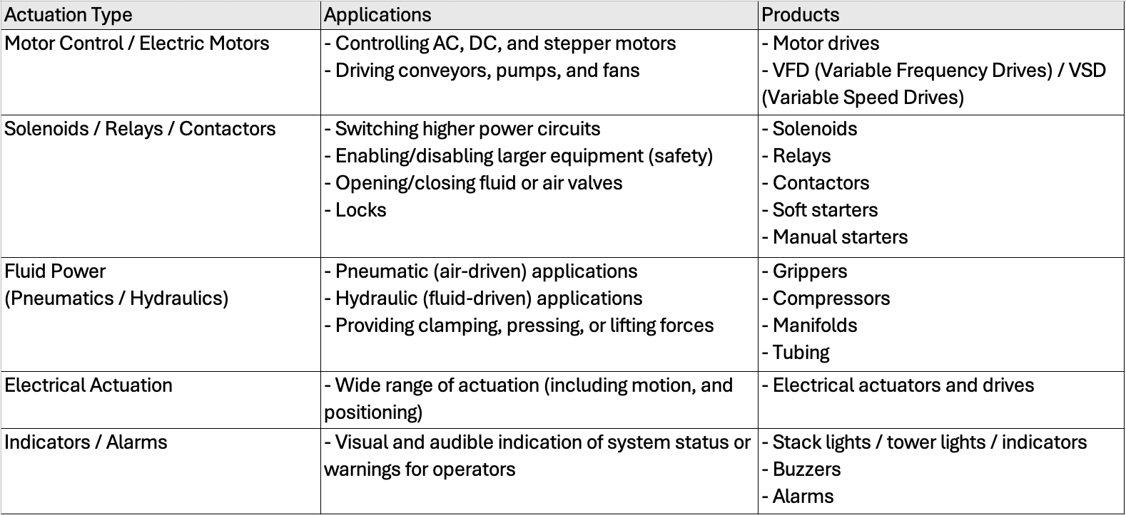 Actuation power sources come in many different types as seen on the chart above
Motor Control / Electrical motors
Electrical motors are one of the simplest applications providing rotational power for Fans, pumps or conveyor belts.
Most motors require additional circuity and components such as motor drives for DC motors or Variable Frequency Drives (VFD) for controlling large AC motors
Solenoids / Relays / Contactors
Electromechanical devices that pass electrical current through a coil to provide movement.
A solenoid is made up of a coil of wire and the moveable plunger placed inside the coil also called an armature. When electrical current is applied to the end of the coil a magnetic field is generated that moves the armature, turning electrical energy into mechanical force. With a quick response time, compact size and simple operation, solenoids are a popular choice in industrial applications such as valve control for fluids and gases.
A relay is a device that uses low power electrical signals to control and switch higher electrical power circuits. A Relay is made up of a coil of wire generating a magnetic field and a separate switch circuit that closes an electrical circuit when the magnetic field is generated. Typically, relays can switch up to a few amps of current and a hundred of volts on the high-power side, but exact power ratings are dependent on the device and application. Relays simplicity and reliable design make them a popular choice for power switching for industrial and automotive applications.
A contactor is a device that uses low power electrical signals to control and switch much higher electrical power circuits. Unlike relays that switch a few amps of electrical current on the switching side of a Contactor. A contactor can switch dozens or hundreds of amps of electrical current and thousands of watts of electrical power. The robust design and internal components of most contactors make them preferred when switching high power electrical loads such as fans and motors.
Mechanical positioning devices, usually powered by a rotational motion source like an electrical motor which is mechanically converted to create linear motion. This includes
- Ball screw driven using ball bearings between the central shaft and nut used in applications needing a high level of accuracy and stability
- Lead screw driven for applications requiring a low-cost and simplicity
- Belt driven using a toothed belt to provide motion
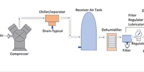
Fluid power (Pneumatics / Hydraulics)
Some automation systems are powered by the movement of pressurized fluid (this could be gases like air or oil). These systems Pneumatic (air-driven) or Hydraulic (fluid-driven) are connected components that can be quickly installed and provide either linear or rotational power to devices.
Pneumatic (air-driven) systems typically operate under low pressure of 60 to 120 PSI powered by an air compressor and properly sized storage tank. Hydraulic (fluid-driven) systems operate at much higher pressures anywhere from 800 to 5000 PSI and have oil as a working fluid. Products include:
Indicators / Alarms
There are several devices that can be connected to automation systems to inform operators of system status and operating conditions. The simplest and most direct are indicator lights and audio alarms.
The classic tower lights can offer a color-coded status light informing staff on the floor of the machine operating status or if there are any error that need to be cleared. While some are simple indicator lights, other tower light devices are networked end terminals and can be remotely controlled or send messages across a network.
Audio devices such as buzzers, speakers or other sound generating can also be used for indicating machine status generating attention on a noisy shop floor.
What is the difference between a soft starter and a VFD ? View Answer
A Soft Starter and Variable Frequency Drive (VFD) are both types of motor starter devices, the design and use of both vary.
Both are semiconductor-based devices used to protect AC induction motors from the high inrush current (this occurs immediately during power on and slowly bring motors up to operational speed).
Most soft starters use a series of thyristors or silicon controlled rectifiers (SCRs) to reduce the inrush current. These get used in mechanical systems such as conveyer belts, or pumps.
A VFD can control the speed of the motor during the start and stop cycle, as well as throughout the run cycle. VFDs convert input power to adjustable frequency and voltage source for controlling speed of AC induction motors.
A soft starter is just focused on ramping up voltage and current.
Popular Actuator Content

Why Use Hydraulic and Pneumatic Actuators VS Electromechanical Actuators
There are times when electromechanical actuators are either too slow or do not have enough power to perform a specific task. As an alternative, pneumatic actuators can provide very high speeds, while hydraulic actuators can deliver staggering amounts of force.
Pneumatic Basics: Understanding Pneumatic Systems in Robotics, Lifts, and Automation
Pneumatics is an engineering field focused on using compressed air or gas to create mechanical motion. Here, the compressed air or gas is directed through various channels to drive mechanical components, like cylinders, actuators, and valves.
The Basics of Motor Contactors and Their Application
This article examines the basics of electromagnetic motor contactors and their advantages over other approaches to motor control. It then discusses how they are selected and applied using real-world configuration examples.
Robotics

The use of robotic ecosystems in industrial automation is steadily growing. In this rapidly growing space, DigiKey has a wide range of robotic systems and components in stock and available for next-day delivery.
For more information about robotic platforms and applications, please visit our Application and Technology page on Robotics.
Also, relevant robotics topics are covered within the DigiKey eMagazines on Robotics.
Industrial Sensors
Industrial sensors are the eyes and ears for PLCs. These sensors, monitor and analyze incoming signals to provide the first step of the feed back loop in process monitoring. These measurements include temperature, pressure, and proximity distances.
Pressure
Pressure sensors can measure the amount of pressure (of gases or liquids). This is usually done to maintain safe and efficient operation within a system. There are a few different types of pressure sensors depending on measuring method being used. Some of the most common include:
- Gauge - relative to current local atmospheric pressure
- Absolute – Measures pressure relative to a perfect vacuum
- Differential – measured the pressure difference between two pressure points, typically between two vessels
Photoelectric
Photoelectric sensors can determine the presence of an object (or measure a distance) by measuring the changes in the transmitted light beam. When the beam of light has been interrupted or blocked from the receiving sensor an object can be inferred, and action can be taken.
Time of flight and distance sensors are similar although they project and receive the light beam back. By measuring the time it takes for a light beam to be reflected off an object a distance measurement can be determined.
Proximity
Proximity sensors can detect presence and distances to objects without physically touching them. Useful for object detection safety interlocks and verifying objects are present (for quality control).
Here are some common methods that proximity sensors operate based on:
- Inductive - by detecting changes in rapidly changing electromagnetic field project outward from the sensor, an inductive sensor can detect the present of a ferrous (iron) and non-ferrous (non-iron based) metal objects.
- Capacitive - as a metallic and non-metallic object approaches the capacitive sensor it disrupts the electrostatic field by changing.
- Magnetic - the presence of a magnetic field approaching the sensor face can be detected by the changes in output by Giant magneto resistive (GMR) sensors or resonant circuits, useful for detecting when a known object is approaching like a safety door or tool head.
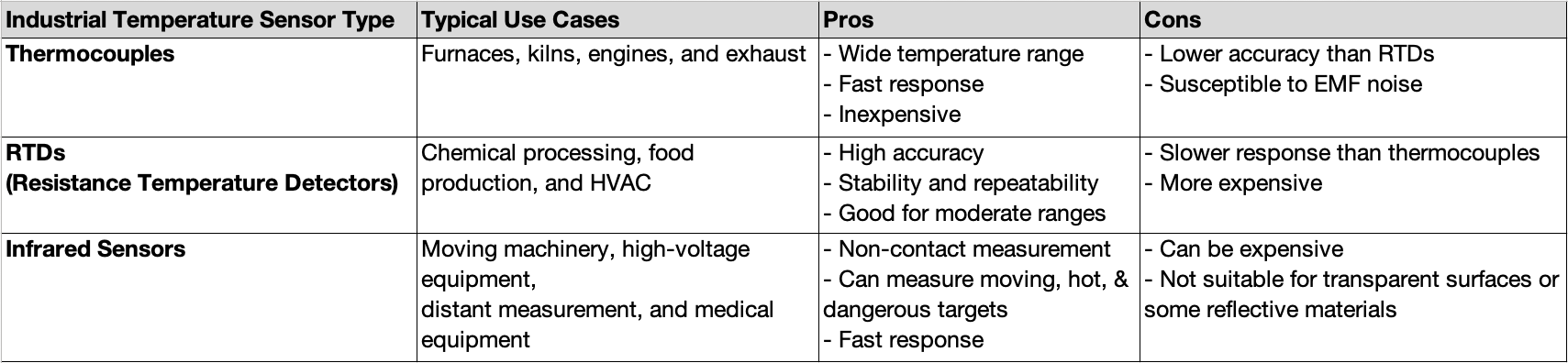
Temperature
 Sample Image Text
Temperature sensors measure thermal conditions and local temperature in process for control and monitoring and to avoid overheating and thermal runaway conditions. Temperature sensors can either be contact and changing electrical properties or by measuring the infrared energy given off.
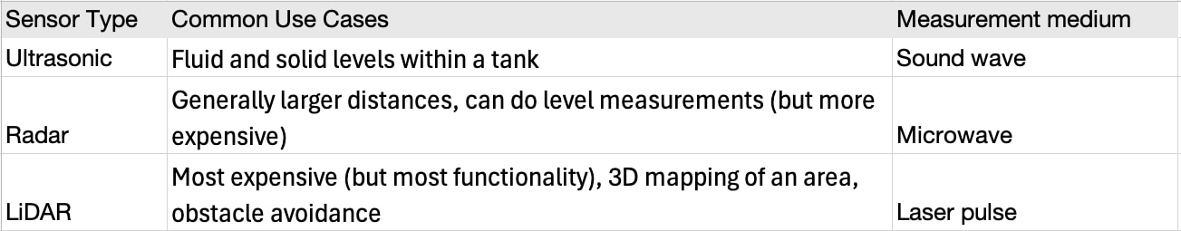
Distance
 Sample Image Text
Determining the distance from a sensor to an object (either stationary or moving) is of great importance to the modern factory. AMRs and other robotic platforms can navigate and make sure the work area is clear of any obstructions.
- Ultrasonics: A transmitter emits a short burst of high-frequency sound waves. When this pulse of sound hits an object, some of the sound waves are reflected to the receiver. A common application for ultrasonic sensors is contactless liquid and fluid level measurement within a tank.
- Radar: Like ultrasonics, radar sensors send out short bursts of high-frequency energy and measure distance based on the time it takes for the reflection to bounce off the surface. Instead of sound waves, radar uses microwave radio waves.
- Lidar: By rapidly spinning a light source like a laser and calculating the time it takes for the light to return to the receiver Distance from the LiDar sensor can be found. Much like Radar it allows for high accuracy.
Rotational
The speed of a rotating shaft or position of the slider can be measured by an encoder, which is an electro-mechanical device that converts the position or motion of a shaft or axle to analog or digital output signals.
Force and Load Cells
Load cells convert forces (like weight, compression, tension, or torque) into measurable signals. As the force applied changes, the output signal changes proportionally. Load cells are commonly used in industrial applications to control weight capacity, measure products, or track weight changes over time.
Popular Industrial Sensor Products

Popular Industrial Sensor Content

Introduction to the Inductive Proximity Sensor
The inductive proximity sensor is commonly used to detect the presence or absence of metal in industrial control systems. As implied by the name, the sensor applies an AC signal to an inductor located in the head of the device.

Industrial sensors - eMagazine
As Industry 4.0 continues to revolutionize manufacturing and automation, the focus on optimizing communication architectures takes center stage. We explore how multi-protocol I/O hubs and converters are streamlining data exchange, making systems more agile and interoperable.

Sorting Through Proximity and Distance Sensor Technology Choices
Using proximity and distance sensors to detect the presence and location of items without physical contact can be an important aspect of controlling industrial processes like material handling, agricultural machinery, fabrication and assembly operations, and food, beverage, and pharmaceuticals packaging.
Safety
Disclaimer: The following information is for educational use only and does not represent safety consulting or design verification. Please consult with a qualified safety technician or inspector before working on any equipment and always be sure to read and follow any safety instructions that come with your industrial equipment.
There are many dangers in the modern industrial process from overheating and runaway pressure to energized machines and faulty sensors. It takes a well-designed system with strict standards to keep both the operators and machine protected.
Regulatory Agencies
-
Occupational Safety and Health Administration (OSHA) - United States government agency within the US Department of Labor sets workplace safety regulations designed to protect worker and prevent workplace accidents
- Underwriter Labs (UL) – global organization that tests and certifies electronic products for quality and safety.
- National Electrical Manufacturers Association (NEMA) – association electrical equipment that publishes safety standards.
- The International Electrotechnical Commission (IEC) - is an international standards organization that prepares and publishes international standards for all electrical, electronic, and related technologies.
Safety Integrity Level (SIL)
The Safety Integrity Level (SIL) is a functional safety term for the level of risk reduction provided by safety equipment. Based on the IEC 61508 standard there are four levels of SIL with level 1 being the least dependable and level 4 being the most dependable level of safety.
For PLCs this can mean detecting faults, executing safe state, and maintaining the certified operation.
Performance Level (PL)
Performance level (PL) is used to define the likelihood of products to perform safely (thus avoiding dangerous failures). PLe is the lowest likelihood of dangerous failure (0.000001% to 0.00001% probability).
Products
 Safety light curtains are optoelectronic devices used to protect personnel from hazardous machinery. They create an invisible barrier of infrared beams between a transmitter and a receiver pair of devices. When any beam is interrupted, the system sends a signal to stop the machine immediately.
 Operator presence mats are pressure-sensitive safety devices placed on the floor near hazardous machinery. When stepped on, they detect the presence of a person and trigger a control signal, typically to stop or prevent machine operation.
 Safety interlocks are mechanical or electrical, based devices that prevent machinery from operating under unsafe conditions. They are typically installed on movable guards, doors, or access panels to prevent operations when open or misaligned and are integrated into a machine's control system.
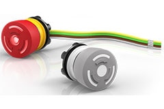
 Emergency stop switches (often called E-Stops) are manually operated safety devices and mechanical switches that are designed to immediately halt machinery or equipment in the event of a hazard.
 Lockout devices are physical safety tools used to isolate switches and prevent the accidental startup of machinery or equipment during maintenance, cleaning, or repair. They are a core part of Lockout/Tagout (LOTO) procedures, which are mandated by OSHA under standard 29 CFR 1910.147.
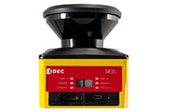
 Laser scanners are non-contact protective devices that use laser beams to monitor defined zones. If a person or object enters a protected area, the scanner sends a signal to stop nearby machinery, preventing injury or damage.
Popular Safety Devices

Popular Safety Content

Engineering Guide to Light Curtains: Selection, Installation, and Safety
This is the index for a series of articles describing safety-critical light curtains. It includes links for selection, mounting, and alignment. It also includes a teardown and description of the essential OSSD waveform used to communicate states with a safety relay.

What are the attributes of an emergency stop pushbutton?
This engineering brief explores the physical and electrical attributes of the emergency stop pushbutton and provide a brief exploration of how this critical safety device is integrated into a larger system.

Webinar – Choosing Sensors and Safety
Selecting a practical sensor solution for operational safety and specific industrial applications can be a complex undertaking. Simplify your search with SICK’s complete industrial sensor offering featuring robust devices for every application and safety scenario.
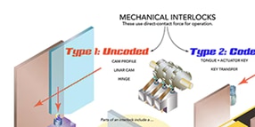
Basics of Safety Interlocks
Keeping plant personnel safe requires that they be protected from mechanical threats to bodily harm. This field of safety engineering is called industrial risk reduction. Local laws and industry standards legally require that automated equipment include various mechanical safety features to prevent dangerous startups
Machine Vision
Machine vision devices enable systems to rapidly view products moving along a conveyor and make real time decisions (often within fractions of a second) such as identifying defects or determining where a product should be diverted. This capability is driven by machine vision software, with models tuned for specific applications including pattern matching, optical character recognition (OCR), barcode decoding, and color analysis.
 Barcode readers and Machine Vision systems may seem similar but have different applications
Barcode Readers
Barcode readers can quickly and efficiently read barcode labels. This could be a 1-dimensional barcode or 2-dimensional square barcode. Due to focused nature of only reading barcode labels these systems are typically easy to implement and have high throughput rates but are unable to do anything but read clear barcode labels. The use of standardized data and consistent label locations makes barcode systems perfect for tracking items and logistics where items passing by a fixed scan location can be read.
Machine Vision Cameras
Machine vision cameras are great at analyzing characteristics of an object and are often used for defect management and quality control of products. By comparing known good images from the training set to the incoming data from cameras, items can be identified as good or defective with minimum human involvement. Machine vision cameras can be used for multiple tasks (including reading barcodes) though operators need to balance resolution and framerates to manage overall bandwidth limitations of the system.
2D vs 3D Vision
 2D and 3D Machine Vision systems have different strengths and weakness
Machine vision can either be 2D or 3D depending on the set up. While there is no single option that is better than the other there are differences between the two:
- 2D is good for understanding surfaces. This can include presence sensing and measurement. 2D vision systems are often used in environments that have more clearly defined distances the objects will be recorded at.
- 3D is good for understanding volumes. This can include sensing depth or measuring the distance to an object. 3D vision systems are typically found in more dynamic environments where objects or pathing could change and accurate measurements are needed.
Popular Machine Vision Products


Popular Machine Vision Content

How Machine Vision is Advancing Automation Now
Machine vision is a collection of technologies that give automated equipment (industrial or otherwise) high-level understanding of the immediate environment from images.

Improve Factory Safety and Productivity by Quickly Adding Machine Vision to Industrial Systems
Designers of machines in industrial automation are being required to implement some form of machine vision to determine the distance from all objects in a specific field of view.
Conveyor Block Diagram
 Block Diagram of a Conveyor System
Circuit Protection and Line Filter


Uninterruptible Power Supply (UPS)
SMPS 24 VDC


Hold up / Buffer


PLC
For more detailed product listing of PLC by application size, please see the first section of page.
IO Modules and Relays
![]()

Phoenix Contact 的 Axioline XC 和 EX I/O 模組設計用於安裝在 Class I、Div 2 環境中,並經過嚴格的 UL-Ex 認證測試。
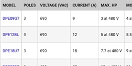
Motor Control
![]()

探索 Schneider Electric 全面的馬達控制解決方案,包括 TeSys™ D 接觸器、Altivar™ 製程驅動器、創新的 Harmony™ 按鈕,提供精準的馬達控制、增強的保護、無縫的整合。

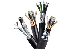
Communications Block
![]()
採用 OPC UA 和 MQTT 介面的 IO-Link 主機
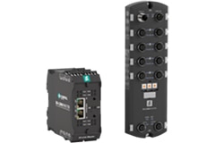
Pepperl+Fuchs IO-Link 主機系列支援業界領先的通訊協定,提供 OPC UA 和 MQTT 介面、即時現場匯流排通訊協定。
Motor
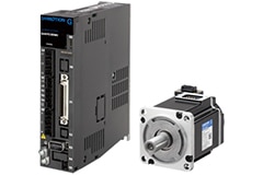
![]()

Schneider Electric Lexium 32 伺服驅動器系列包括四種伺服驅動器型號:LXM32C、LXM32A、LXM32M 和 LXM32S,搭配兩種伺服馬達系列。