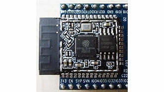
Mfr Part # ESP32-S3-DEVKITC-1-N32R8V
ESP32-S3-WROOM-2-N32R8V DEV BRD
Espressif Systems
As embedded systems grow more complex, developers often need ways to manage and adapt to changing hardware configurations. Instead of hardcoding hardware details directly into the code, modern operating systems and frameworks rely on a flexible hardware description system. Enter Devicetree—an elegant solution that separates hardware descriptions from your application logic.
Devicetree offers a standardized, declarative syntax to specify what hardware your platform contains—GPIO pins, I2C buses, UART peripherals, sensors, and more. By using Devicetree, you can write board-agnostic applications and driver code that seamlessly adapts to new hardware configurations without rewriting logic. While the Linux kernel uses Devicetree at runtime (during boot), Zephyr evaluates it at compile time, ensuring only relevant device drivers and configurations get compiled into your final firmware.
Previously, we looked at using Kconfig to enable and configure various software components. In this post, we’ll cover:
All example code and solutions for this series can be found in this repository: https://github.com/ShawnHymel/introduction-to-zephyr/
In 1988, Sun Microsystems introduced Open Firmware. While Open Firmware itself has fallen by the wayside, one crucial concept lived on: a standardized format to describe system hardware in a hierarchical, tree-like structure. By the early 2000s, embedded Linux developers recognized the need for a method to declare hardware in a more portable and dynamic way, sparking the formalization of Devicetree.
A 2006 paper from OzLabs laid much of the groundwork for what we now call Devicetree. The standard has since evolved into a community-driven specification (see devicetree.org). Today, Devicetree is a cornerstone of Linux-based platforms, helping the kernel understand the hardware layout. Zephyr adopted Devicetree for similar reasons: it provides a systematic way to describe hardware at compile time, allowing Zephyr to include the correct drivers, addresses, and configurations in the final build.
Linux uses the Devicetree to load drivers and modules at runtime (usually during the boot process). While Zephyr does not rely on Devicetree at runtime, it uses the Devicetree’s syntax and semantics to compile in only the hardware drivers and settings you need. This makes your firmware more portable and easier to maintain, as you can simply adjust Devicetree entries without rewriting code.
Portability and Abstraction: By describing hardware in Devicetree rather than code, you can reuse the same driver or application logic across different boards. When you switch MCUs or add new peripherals, you simply adjust the Devicetree to match your new hardware layout. Your code remains the same—just rebuild, and Zephyr picks up the new configuration.
Clarity and Organization: Devicetree files provide a structured view of your hardware. Instead of scattered #defines and macros all over your codebase, hardware configuration lives in Devicetree source (DTS) files. This central reference makes it easier to understand and maintain complex projects.
The official Devicetree specification is available at devicetree.org. It describes the format, reserved properties, and principles behind representing hardware as a hierarchical tree structure.
Some key properties you should be aware of:
For example, a CPU node might be at /cpus/cpu@0. Another node might be /soc/gpio@4000 representing a GPIO controller at memory address 0x4000.
Phandles are references that the Devicetree compiler assigns to nodes so other nodes can reference them. This allows linking related hardware components together without duplication.
Devicetree Source (DTS) files are text-based and look somewhat like a hierarchy of nested braces. Zephyr has a great set of Devicetree reference guides here.
Some key points:
For example:
/dts-v1/;

/ {
    compatible = "my,board";
    a-node {
        a-sub-node: a-sub-node {
            some-property = <0x1234>;
        };
    };
};
You can reference a-sub-node either by its full path /a-node/a-sub-node or by its label a-sub-node.
Nodes contain zero or more properties, which can be thought of as variables that contain numbers, strings, arrays, etc. I found this table to be quite helpful in understanding the different property types.
Nodes sometimes have @ followed by a unit address. This is a human-readable hint, often matching a memory address or bus number. The actual address is defined by a property named reg. For example:
gpio0: gpio@4000 {
    compatible = "myvendor,mygpio";
    reg = <0x4000 0x1000>;
    status = "okay";
};
Here gpio0 is a label, gpio@4000 is the node’s name, and reg defines its memory address range. The “@4000” part of the name is just a string; by convention, it should match the address given in the reg property. compatible specifies which driver should be used, while status = "okay" means this hardware is enabled.
Aliases are shortcuts for paths. They are defined in the “aliases” node just under the root (/) node. The Zehpyr Devicetree compiler (DTC) looks for this node to assign aliases. For example, if your application always references a certain UART, you can define an alias:
/ {
    aliases {
        my-uart = &uart0;
    };
};
Now, my-uart can be used in code to reference the UART0 node without remembering its full path or label. Aliases are a great way to maintain portable code, as your application code can reference the alias while the specific Devicetree and driver implementations can change based on the hardware.
Chosen nodes are special; like aliases, the DTC looks for a “chosen” node just under root (/). They help select which node corresponds to core functions like the console. For example, you might have:
/ {
    chosen {
        zephyr,console = &uart0;
    };
};
This tells Zephyr’s logging and console infrastructure to use uart0 as the system console.
While alias properties are defined by the user, chosen properties have special meaning in Zephyr. This table gives you a list of Zephyr-specific chosen properties. Zephyr uses these chosen properties to enable and configure various drivers and hardware.
Zephyr projects often have multiple DTS and DTSI (Devicetree Source Include) files. The .dtsi files are included by .dts files, much like C headers, providing a way to share common configurations (like SoC definitions or board-level specifics).
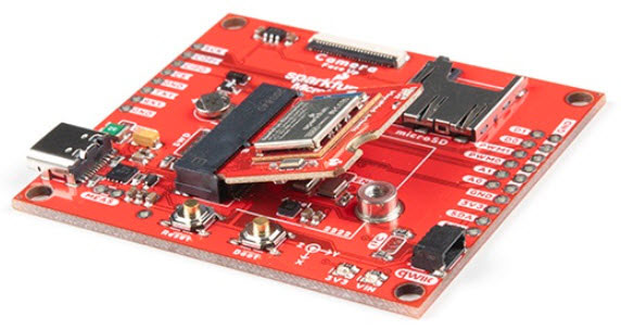
For instance, the ESP32-S3 DevKitC board’s configuration might involve several layers:
You’ll see #include directives in these files. They allow building a Devicetree hierarchy by layering configurations: starting with a base SoC definition and adding or overriding properties for your specific board. In some cases, these include files will contain Devicetree nodes/properties (e.g., in a .dtsi file) or C-style header definitions (e.g., in a .h file). These C-style macros allow the developer (or vendor) to map human-readable names to hardcoded values, such as pin names or interrupt priority levels.
If you search for gpio in esp32s3_common.dtsi, you’ll see something like:
gpio0: gpio@60004000 {
    compatible = "espressif,esp32-gpio";
    reg = <0x60004000 0x1000>;
    ...
    status = "okay";
};
This defines the first GPIO controller (gpio0). You can then reference the label &gpio0 in your board’s DTS or overlay files to configure pins as inputs or outputs for particular drivers or peripherals.
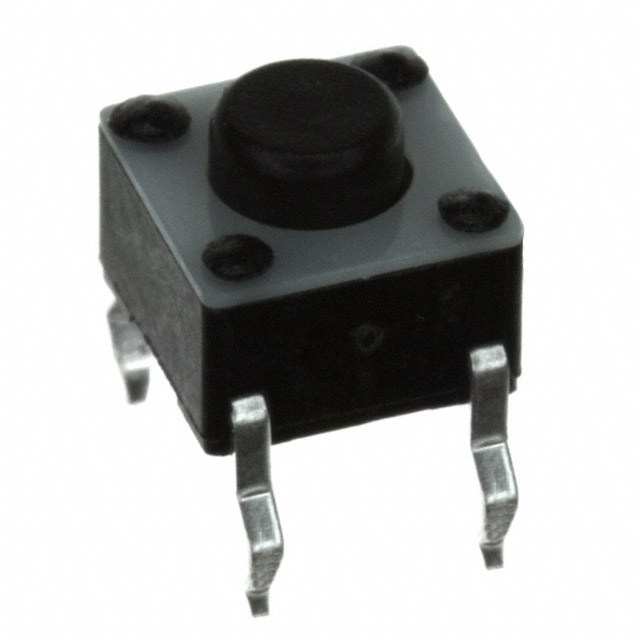
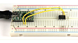
Let’s apply what we’ve learned. We’ll create a simple button input on the ESP32-S3 and read its state in our application code. This example helps illustrate how overlay files and Devicetree references work.
Note that we’ll be using the Docker image found in this repository to configure our Zephyr development environment: https://github.com/ShawnHymel/introduction-to-zephyr/
Create a new project directory structure:
/workspace/apps/04_demo_button/
├─ boards/
│  └─ esp32s3_devkitc.overlay
├─ src/
│  └─ main.c
├─ CMakeLists.txt
└─ prj.conf
cmake_minimum_required(VERSION 3.22.0)

find_package(Zephyr REQUIRED HINTS $ENV{ZEPHYR_BASE})
project(button_demo)

target_sources(app PRIVATE src/main.c)
prj.conf
Leave empty
boards/esp32s3_devkitc.overlay
Overlay files allow you to add or modify Devicetree nodes at build time without editing the board’s original .dts files. In boards/esp32s3_devkitc.overlay:
/ {
    aliases {
        my-button = &button_1;
    };

    buttons {
        compatible = "gpio-keys";
        debounce-interval-ms = <50>;
        polling-mode;

        button_1: d5 {
            gpios = <&gpio0 5 (GPIO_ACTIVE_LOW | GPIO_PULL_UP)>;
        };
    };
};
Here’s what this does:
You can define an overlay file anywhere in your project, and you will have the option to include it during the build process. Note that in most cases, overlay files are used to define a particular hardware configuration for a board, which is why we keep it in the boards/ directory.
#include <stdio.h>
#include <zephyr/kernel.h>
#include <zephyr/drivers/gpio.h>

// Settings
static const int32_t sleep_time_ms = 100;
static const struct gpio_dt_spec btn = GPIO_DT_SPEC_GET(DT_ALIAS(my_button), gpios);

int main(void)
{
    int ret;
    int state;

    // Make sure that the button was initialized
    if (!gpio_is_ready_dt(&btn)) {
        printk("ERROR: button not ready\r\n");
        return 0;
    }

    // Set the button as input (apply extra flags if needed)
    ret = gpio_pin_configure_dt(&btn, GPIO_INPUT);
    if (ret < 0) {
        return 0;
    }

    // Print out the flags
    printk("Button spec flags: 0x%x\r\n", btn.dt_flags);

    // Do forever
    while (1) {

        // Poll button state
        state = gpio_pin_get_dt(&btn);
        if (state < 0) {
            printk("Error %d: failed to read button pin\r\n", state);
        } else {
            printk("Button state: %d\r\n", state);
        }

        // Sleep
        k_msleep(sleep_time_ms);
    }

    return 0;
}
This code uses GPIO_DT_SPEC_GET to retrieve the button configuration from Devicetree by referencing the my_button alias. It then configures the pin as input and prints its state every 100 ms.
Build with:
west build -p always -b esp32s3_devkitc/esp32s3/procpu -- -DDTC_OVERLAY_FILE=boards/esp32s3_devkitc.overlay
DTC_OVERLAY_FILE tells Zephyr’s build system to apply our overlay on top of the board’s default DTS configuration. After building, inspect the generated build/zephyr/zephyr.dts to see how the overlay is merged into the final Devicetree. The DTC pulls in various Devicetree fragments (.dts, .dtsi, .overlay) from all over the Zephyr source code, including:
Flash and run the application on the board. By pressing or releasing the button connected to GPIO pin 5, you’ll see the printed state change.

We’ve touched on compatible and how Devicetree matches devices to drivers. Each compatible value corresponds to a binding, usually defined in YAML files. Bindings explain how to interpret node properties. Zephyr uses these bindings to verify that properties are valid and to generate APIs and definitions for your code.
For example, the gpio-keys compatible expects certain properties that describe keys (buttons) and their GPIO connections. Drivers and subsystems read these properties to know how to initialize and manage the hardware.
In this Zephyr series, we will continue building upon these concepts to ultimately write our own device driver.
The Devicetree specification and the Linux kernel community have established conventions for node names, properties, and labels:
For more guidance, see the Devicetree specification and the Zephyr Devicetree documentation.
Integrate the button logic with your LED blinking example from the first tutorial. Use the button’s state to enable or disable LED output. This will give you practice in merging Devicetree configurations, interacting with multiple peripherals, and increasing the hardware abstraction in your embedded application.

In this post, we explored the Devicetree syntax and demonstrated how it can be used to configure hardware in a Zephyr project. If you’d like to dive more into the Devicetree syntax, I recommend the following resources:
In the next tutorial, we’ll look at how bindings files provide the glue between the Devicetree and device driver code. After that, we’ll actually build our own device driver so you can see how all these systems work together.