Mfr Part # OPA182IDR
36-V, 5-MHZ, SINGLE, LOW-NOISE,
Texas Instruments
There are multiple ways of thinking about the Input Offset Voltage (Vos) of an operational amplifier. One commonly thrown-around definition is that Vos is the voltage you have to apply between the inputs to zero the output. When I first read about this, I thought it was a slightly confusing way of phrasing it (although in hindsight it sounds simple, which it is). I prefer looking at it through an equation:
We know that the ideal op amp equation is:
Vout = AOL * (VP - VM)
Where AOL is the open-loop gain, and VP and VM are the non-inverting and inverting terminals of the op amp.
With Vos in mind, we have:
Vout = AOL * (VP - VM + Vos)
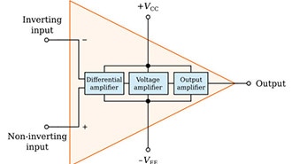
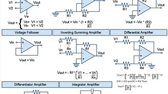
Thus, Vos is essentially an ever-present error that exists between the input terminals of the device. We can better understand this by looking at the fundamental building block of an op-amp, the differential amplifier:

In this circuit, the two transistors are connected to a current source. Ideally, since they are perfectly matched, it should follow that the current is the same through both branches, which is what we see. However, that assumption does not hold in real life -- the devices are not perfectly matched. Since they aren't matched, the voltage on the output will have some non-zero value even if the inputs are held at the same value.
Typically, this offset voltage will be decently small -- in the order of mV at most. For most applications, this is usually fine. However, let's think about a practical example where this offset voltage can be detrimental.
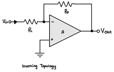
One type of audio signal is the phono input. A phono cartridge will output very, very low output signals, in the mV range. Let's say we had a 2 mV peak signal and we wanted an output level of 2 volts peak. That would require a gain of 1000. If we use an amplifier with a Vos of 1 mV configured for a gain of 10:
Vout = 1000 * (0.002V + 0.001V) = 3 V
Now you have a volt of offset on your signal! Before you say, "Why can't you just high-pass filter the DC offset away?" -- you can, but it's not always that easy: some signals can be pretty slow and thus hard to effectively filter, this can also be inside a closed-loop system -- so putting a filter can destroy the stability of your control loop, etc. So... it's not really that easy to fix.
Many modern operational amplifiers are manufactured with excellent tolerances or use fancy design techniques in order to achieve very low Vos -- in the microvolt range. Namely, Chopper-stabilized amplifiers are a special architecture of op-amp that utilizes a switching modulation scheme to drive away the DC offset, allowing you to get really low offsets, like 1 uV, for example.
If we used the OPA182, we could get really low Vos -- let's go for the worst case of 4 uV as per the datasheet. Thus:
Vout = 1000 * (0.002V + 4*10^-6 V) = 2.004V -- a 0.2% error (a DC offset of 4 mV). Not bad!

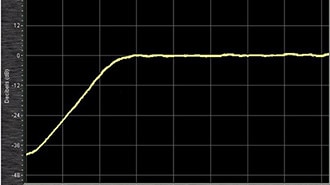
Just remember, the input offset voltage can vary greatly with temperature, age, and other external conditions. Manufacturers will typically include graphs detailing these errors. As always: read the datasheet!