A Deep Dive into SCRs and Their Impact on Electronics
2024-04-22 | By DWARAKAN RAMANATHAN
Introduction:
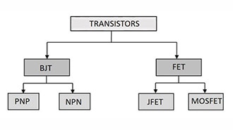
A Silicon Controlled Rectifier (SCR) is a four-layer solid-state current-controlling device. It is also known as a Thyristor. The device is made up of four alternating layers of p-type and n-type semiconductor material, forming three p-n junctions. The SCR is capable of controlling high-power AC and DC circuits, making it useful in a variety of applications such as motor control, lighting control, and power conversion.
The SCR is triggered by a gate signal and becomes a true amplifying device. It has three modes of operation depending upon the biasing given to it: forward blocking mode (off state), forward conduction mode (on state), and reverse blocking mode (off state). In the forward blocking mode, the anode (+, p-doped side) is given a positive voltage while the cathode (−, n-doped side) is given a negative voltage, keeping the gate at zero (0) potential i.e., disconnected. In this case, junctions J1 and J3 are forward-biased, while J2 is reverse-biased, allowing only a small leakage current from the anode to the cathode. When the applied voltage reaches the breakover value for J2, then J2 undergoes avalanche breakdown. At this breakover voltage, J2 starts conducting, but below breakover voltage, J2 offers very high resistance to the current, and the SCR is said to be in the off state.
Symbol and Structure:
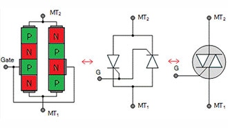
 The left diagram shows the structure of the SCR, and the right diagram shows the Symbol of an SCR
Operating Modes:
As previously mentioned, Silicon Controlled Rectifiers (SCRs) operate in three main modes: forward blocking mode (off state), forward conduction mode (on state), and reverse blocking mode. In the forward blocking mode, the SCR is non-conductive, and no current flows between the anode and cathode. Upon receiving a trigger signal, the SCR enters the forward conduction mode, allowing current to flow. Once triggered, it remains in the on state until certain conditions are met. In reverse blocking mode, the SCR blocks current flow in the reverse direction, similar to a diode in reverse bias. The SCR transitions between these modes based on external factors, making it a versatile device for controlling power in various electronic applications.
1. Reverse blocking mode (OFF state)
Anode: Negative terminal
Cathode: Positive terminal
Gate: Open
Outer junctions J1 and J3 are reverse biased, inner junction J2 is forward biased
With the increase in VAK, the width of J1, J3 increases, and J2 decreases
A small amount of current from the cathode to anode flows in the name of reverse leakage current
SCR is still in off-condition

2. Forward blocking mode (OFF state)
Anode: Positive terminal
Cathode: Negative terminal
Gate: Open
Outer junctions J1 and J3 are forward biased, inner junction J2 is reverse biased
With the increase in VAK width of J1 J3 decreases and J2 increases
A small amount of current from the Anode to the Cathode flows in the name of reverse leakage current
SCR is still in off-condition

3. Forward conduction mode (ON state)
Anode: Positive terminal
Cathode: Negative terminal
Gate: Positive Current
SCR can be brought from blocking mode to conduction mode in two ways either by increasing the voltage across anode to cathode beyond break over voltage or by applying a positive pulse at the gate
Positive gate current injects more charges in the second P layer which leads to the breakdown of junction
J2 with a small VAK
SCR is in On-condition

Once SCR starts conducting, current flows from the Anode to the Cathode. Also, there is no need for gate pulse after the Turn ON which leads to gate drive loss.
The latching current is defined as the minimum value of the anode current which it must attain during the turn-on process to maintain conduction when the gate signal is removed.
The holding current is defined as the minimum value of the anode current below which it must fall to Turn OFF the thyristor.
VI Characteristics:
The voltage current (VI) characteristics of a Silicon Controlled Rectifier (SCR) describe the relationship between the voltage across its terminals (anode and cathode) and the current flowing through it. The VI characteristics of an SCR can be explained in different regions:
- Forward Blocking Region (Off State):
- In this region, the SCR is in the off state.
- The applied forward voltage is below the forward breakdown voltage.
- There is negligible current flow, and the SCR acts like an open circuit.
- Forward Conduction Region (On State):
- When the applied forward voltage exceeds the forward breakdown voltage and a gate signal is applied, the SCR enters the on state.
- In this region, the SCR becomes highly conductive, allowing a significant current to flow.
- The voltage drop across the SCR is relatively low, and it behaves like a closed switch.
- Holding Current Region:
- Even after triggering, the SCR remains in the on state until the anode current falls below a certain level called the holding current.
- If the current drops below this threshold, the SCR returns to the forward blocking state.
- Reverse Blocking Region:
- In this region, a reverse voltage is applied across the SCR, causing it to block current flow in the reverse direction.
- The reverse breakdown voltage is the maximum reverse voltage the SCR can withstand without allowing significant reverse current.

Applications of SCR:
- Power Control:
- SCRs are widely used for controlling power in industrial applications. They are employed in phase-angled fired controllers to regulate the power supplied to resistive loads, such as electric heaters.
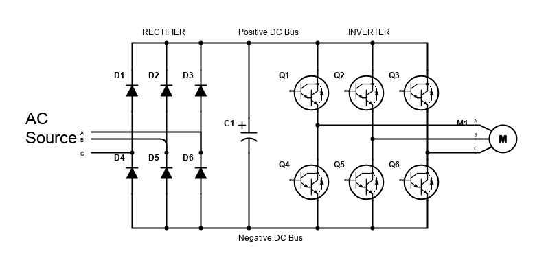
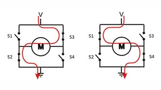
- Motor Control:
- SCRs are utilized in motor control circuits, particularly in variable-speed drives. By adjusting the firing angle of the SCR, the speed and torque of the motor can be controlled efficiently.
- Light Dimming Systems:
- In lighting systems, SCRs are employed to control the intensity of lamps by regulating the power supplied to them. This is commonly used in dimmer switches for residential and commercial lighting.
- Rectifier Circuits:
- SCRs are often used in rectifier circuits to convert alternating current (AC) to direct current (DC). Their controllable switching capability allows for efficient DC power control.
- Voltage Regulation:
- SCRs are used in voltage regulators to maintain a stable output voltage. This is crucial in applications where a consistent voltage level is required, such as in power supplies.
Advantages of SCR:
- High Current and Voltage Ratings:
- SCRs can handle high currents, often in the range of tens or hundreds of amperes, and high voltages, typically ranging from several hundred to thousands of volts. This makes them suitable for high-power applications.
- Low Conduction Losses:
- SCRs have low forward voltage drop when in the on-state, resulting in minimal conduction losses. This characteristic contributes to their high efficiency in power control applications.
- Gate Control for Triggering:
- SCRs are triggered into conduction by applying a small gate current. This gate control mechanism allows for precise and rapid switching, making them suitable for applications where accurate control is essential.
- High Switching Speed:
- SCRs exhibit fast switching speeds, enabling quick response times in applications that require rapid changes in power levels.
- Robust and Reliable Operation:
- Once triggered, SCRs remain in the on-state until the current falls below a certain threshold or the voltage becomes reverse-biased. This characteristic contributes to the robust and reliable operation of SCRs.
Conclusion:
Silicon Controlled Rectifiers (SCRs) stand as formidable components in the realm of power electronics, offering a compelling array of advantages. Their high current and voltage handling capabilities, coupled with low conduction losses, make them indispensable for applications demanding robust power control. The precision of gate control, fast switching speeds, and reliability further underscore their significance in various industries, from motor control to lighting systems. With solid-state construction, temperature stability, and a compact design, SCRs exemplify efficiency and longevity. As we navigate the ever-evolving landscape of electronic applications, the versatility and cost-effectiveness of SCRs position them as pivotal players in shaping the future of high-power electronics. Whether driving industrial processes or enhancing energy efficiency, the enduring appeal of SCRs lies in their ability to seamlessly merge technical prowess with practical utility, marking them as enduring fixtures in the intricate tapestry of electronic innovation.