Mfr Part # 12650
EVAL BOARD FOR AD8232
SparkFun Electronics
License: Attribution Board / Sensor Interface Cables Arduino
As a senior electrical engineering student, I’ve been working hard on my senior design project. My senior design project is sponsored by a veterinarian in New York, and we are working to design a cardiac monitoring device for pets. To do this, my project partner and I needed to learn about how to get an ECG signal like you would see at the doctor’s office. ECG stands for Electrocardiogram and can also be written as EKG. An ECG is a test that records the electrical signals of the heart. It shows how the heart is beating and can help diagnose heart problems, such as arrhythmias or heart attacks.
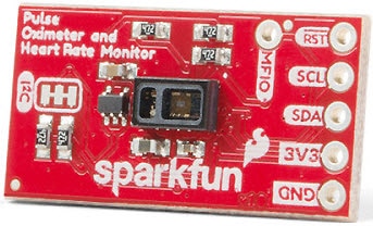
In our project, we are using the SparkFun Single Lead Heart Rate Monitor-AD8232, which is a very cost-effective development board used to measure the electrical activity of the heart. Because every time muscles expand or contract, they also release electrical signals, reading the electrical signals of only the heart can be very noisy. However, the AD8232 acts as an op amp to help obtain a clear signal. Here is a functional block diagram of the AD8232, which can be found in the datasheet. When it comes to working with a new chip, you should always check out the datasheet. The best part about using SparkFun products, however, is that they do a lot of the circuitry and protection for you.
Okay, let’s get into the basics of using this board. For this project, you can use an Arduino as an output or an oscilloscope, depending on what you have at your disposal and whether you would like to code. In this example, I will use an oscilloscope and provide code for the Arduino Pro Mini 3.3V/8 MHz, which can be purchased here. To connect the Arduino to a computer, I’m using a SparkFun FTDI Basic Breakout 3.3V and a USB mini-B cable. The code provided should be adaptable to any Arduino. The AD8232 Heart Rate Monitor has nine connections from the IC. On this board, they are labeled RA, LA, RL, GND, 3.3V, Output, Lo-, Lo+, and SDN. You can solder header pins or wires to these spots. If you’re using an Arduino for this project, the five pins you will need are GND, 3.3V, Output, Lo-, and Lo+. If you’re using an oscilloscope as an output instead, you can use 3.3V, GND, and output. Lo- and Lo+ are used for lead on-off detection.
If using Arduino, connect GND to GND, 3.3V to 3.3V, Output to A0, Lo- to Pin 11, and Lo+ to Pin 10.
If you use an oscilloscope, you’ll need to connect 3.3V and GND to a DC Power Supply and output to your oscilloscope.
Now that the wiring is complete, you’ll want to connect the end of the electrode wires that look like a headphone jack to the black connector on the AD8232. Then, snap the single-use electrodes into the rounded end of the electrode cable.
When it comes to placing the electrodes on your body, you’ll want to place them as close to the heart as possible for better measurement. The cables are color-coded with black, placed closest to the right arm. Blue is placed closest to the left arm, and red is placed on the right leg. These positions are based on Einthoven’s triangle. In the diagram below, you can see two of the best options for electrode placement.
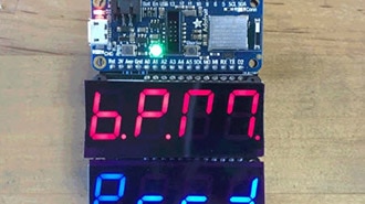
An Arduino program provided by SparkFun can be found here. You can copy and paste the code from GitHub or download the repository. To verify that the heart rate monitor is working as expected, open the serial monitor at 9600 baud. If you see values between +- 500, then the sensor is working. Then, if you open the serial plotter, you should see an ECG waveform.
If you are using an oscilloscope, simply connect 3.3V, GND, and output and scale the scope accordingly. Below you can see the oscilloscope waveform of my heart. As you can see, the output waveform is between +- 500mV, even though the actual electrical signals of the heart are only +- 25mV. This is because the signal is amplified in the AD8232. The frequency of a human heart is also ~ 60Hz, which is what we can see on the screenshot from the oscilloscope.
Now, you should be able to go ahead and look at your own ECG or even a friend’s. It’s a neat tool that has many applications, including a stress monitor, a lie detector, or just as something fun to experiment with. You now know the basics, so the rest is up to you.
Note: This product is NOT a medical device and is not intended to be used as such or as an accessory to such, nor to diagnose or treat any conditions.