Mfr Part # 5325
STEMMA QT QT PY ESP32-S2 WIFI
Adafruit Industries LLC
License: See Original Project 3D Printing Wearables ESP32 STEMMA
Courtesy of Adafruit
Guide by Liz Clark
Overview
When you're out and about at a convention or conference sometimes you want to be a social butterfly, but other times you'd prefer to float anonymously amongst the crowds. In this project, you'll build a conference badge utilizing a tiny traffic light that you can use to symbolize to the world your socializing preferences in the moment:
Red for "no socializing please"
Yellow for "lets connect if we really know each other"
Green for "I want to talk to every single person"
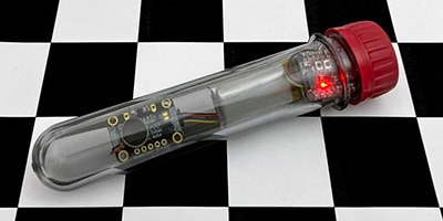
The badge uses a QT Py ESP32-S2 with a LiPo BFF running CircuitPython. This makes for an ultra-portable electronics solution with code you can customize even while you're at the con.
The badge is themed as a tiny road diorama to match the mini traffic light model. You can paint and customize the case with model accessories such as grass, plants, or other small details.
There is a cutout in the case for a STEMMA cable. You can use it for additional electronics, plugging in SAO boards or adding your favorite STEMMA sensor.
Parts
1 x Silicone wire - various colors
1 x Heat shrink
Diorama Parts and Paint
1 x Mini Green Grass
1 x Mini Meadowland Bushes
1 x Acrylic paint
1 x E6000 glue
Circuit Diagram
Button
Button output to board pin A0
Button ground to board GND
Traffic Light
Red wire to board pin A1
Yellow wire to board pin A2
Green wire to board pin A3
Black wire to board 3V
3D Printing
The badge may be housed in a 3D printed case, described below. The case consists of three parts: a bottom lid, a main badge case, and a tiny manhole cover. The main badge case benefits from some supports.
The STL files can be downloaded directly here or from Thingiverse.
You can use support blockers in your slicer software to only have supports in the center of the main badge case. This should provide enough support for your printer to bridge the wall.
The badge has slots and cutouts for the button, traffic light, and QT Py ESP32-S2's STEMMA cable. If you don't want to use the STEMMA cable, you can cover the hole with the tiny manhole cover.
Painting
You can print the parts in white PLA so that you can paint the different details of the badge. Acrylic paint works great for covering PLA.
You can add diorama grass and plants on the side of the road. Add a thin layer of E6000 glue over the surface of the grass area and sprinkle the grass on top.
CircuitPython
CircuitPython is a derivative of MicroPython designed to simplify experimentation and education on low-cost microcontrollers. It makes it easier than ever to get prototyping by requiring no upfront desktop software downloads. Simply copy and edit files on the CIRCUITPY drive to iterate.
CircuitPython Quickstart
Follow this step-by-step to quickly get CircuitPython running on your board.
Download the latest version of CircuitPython for this board via circuitpython.org
Click the link above to download the latest CircuitPython UF2 file.
Save it wherever is convenient for you.
Plug your board into your computer, using a known-good data-sync cable, directly, or via an adapter if needed.
Click the reset button once (highlighted in red above), and then click it again when you see the RGB status LED(s) (highlighted in green above) turn purple (approximately half a second later). Sometimes it helps to think of it as a "slow double-click" of the reset button.
For this board, tap reset and wait for the LED to turn purple, and as soon as it turns purple, tap reset again. The second tap needs to happen while the LED is still purple.
Once successful, you will see the RGB status LED(s) turn green (highlighted in green above). If you see red, try another port, or if you're using an adapter or hub, try without the hub, or different adapter or hub.
If double-clicking doesn't work the first time, try again. Sometimes it can take a few tries to get the rhythm right!
A lot of people end up using charge-only USB cables and it is very frustrating! Make sure you have a USB cable you know is good for data sync.
If after several tries, and verifying your USB cable is data-ready, you still cannot get to the bootloader, it is possible that the bootloader is missing or damaged. Check out the Install UF2 Bootloader page for details on resolving this issue.
You will see a new disk drive appear called QTPYS2BOOT.
Drag the adafruit_circuitpython_etc.uf2 file to QTPYS2BOOT.
The BOOT drive will disappear, and a new disk drive called CIRCUITPY will appear.
That's it!
Coding the Traffic Light Conference Badge
Once you've finished setting up your QT Py ESP32-S2 with CircuitPython, you can access the code and necessary libraries by downloading the Project Bundle.
To do this, click on the Download Project Bundle button in the window below. It will download as a zipped folder.
# SPDX-FileCopyrightText: 2022 Liz Clark for Adafruit Industries
# SPDX-License-Identifier: MIT

import time
import board
import alarm
from digitalio import DigitalInOut, Direction, Pull
#  setup pins for the traffic light LEDs
red_light = DigitalInOut(board.A1)
yellow_light = DigitalInOut(board.A2)
green_light = DigitalInOut(board.A3)
#  array of LEDs
lights = [red_light, yellow_light, green_light]
#  the traffic light is common anode
#  the pins will need to be pulled down to ground
#  to turn on the LEDs. they are setup as inputs
#  so that the pull can be toggled
#  Pull.UP turns the LEDs off to start
for light in lights:
    light.direction = Direction.INPUT
    light.pull = Pull.UP
#  button pin setup
pin_alarm = alarm.pin.PinAlarm(pin=board.A0, value=False, pull=True)
#  count to track which light is on
count = 2
#  tracks the last light
last_count = 1
while True:
    #  increase count by 1, loop through 0-2
    count = (count+1) % 3
    #  turn off the last LED
    lights[last_count].pull = Pull.UP
    #  turn on the current LED
    lights[count].pull = Pull.DOWN
    #  print(count)
    #  delay to keep count
    time.sleep(1)
    #  reset last LED for next loop
    last_count = count
    #  go into light sleep mode until button is pressed again
alarm.light_sleep_until_alarms(pin_alarm)Upload the Code and Libraries to the QT Py ESP32-S2
After downloading the Project Bundle, plug your QT Py ESP32-S2 into the computer's USB port with a known good USB data+power cable. You should see a new flash drive appear in the computer's File Explorer or Finder (depending on your operating system) called CIRCUITPY. Unzip the folder and copy the following items to the QT Py ESP32-S2's CIRCUITPY drive.
lib folder
code.py
Your QT Py ESP32-S2 CIRCUITPY drive should look like this after copying the lib folder and the code.py file.
How the CircuitPython Code Works
The traffic light model's LEDs are common anode, meaning that the three LEDs share power (the black wire). The red, yellow, and green wires need to be tied to ground to turn on the LEDs.
In the code, the three LEDs' pins are set as inputs so that their pull direction can be toggled either UP or DOWN. When a pin's pull is set to Pull.UP, the LED is off. When a pin's pull is set to Pull.DOWN, the pin is tied to ground and the LED turns on.
#  setup pins for the traffic light LEDs
red_light = DigitalInOut(board.A1)
yellow_light = DigitalInOut(board.A2)
green_light = DigitalInOut(board.A3)
#  array of LEDs
lights = [red_light, yellow_light, green_light]
#  the traffic light is common anode
#  the pins will need to be pulled down to ground
#  to turn on the LEDs. they are setup as inputs
#  so that the pull can be toggled
#  Pull.UP turns the LEDs off to start
for light in lights:
    light.direction = Direction.INPUT
    light.pull = Pull.UP
PinAlarm
The ESP32-S2 has the ability to use deep_sleep and light_sleep to save battery life. sleep can be exited with alarms using the alarm library. One type of alarm is a PinAlarm where if a pin's state changes, then sleep is interrupted. In this case, the button's pin is setup as pin_alarm.
#  button pin setup
pin_alarm = alarm.pin.PinAlarm(pin=board.A0, value=False, pull=True)
Variables
count and last_count keep track of the button presses. The count determines which LED in the traffic light is turned on.
#  count to track which light is on
count = 2
#  tracks the last light
last_count = 1
The Loop
In the loop, count increases by 1 for a range of 0 to 2. The last LED that was turned on has its pull set to Pull.UP to turn it off. The current LED is turned on by setting its pull to Pull.DOWN. Finally, the ESP32-S2 goes into light_sleep to preserve battery life. It will stay in this state until the button is pressed again. Once the button is pressed, the loop will repeat.
while True:
    #  increase count by 1, loop through 0-2
    count = (count+1) % 3
    #  turn off the last LED
    lights[last_count].pull = Pull.UP
    #  turn on the current LED
    lights[count].pull = Pull.DOWN
    #  print(count)
    #  delay to keep count
    time.sleep(1)
    #  reset last LED for next loop
    last_count = count
    #  go into light sleep mode until button is pressed again
    alarm.light_sleep_until_alarms(pin_alarm)
Solder the ESP32-S2 and Lipoly Charger BFF
Solder the short end of the headers to the LiPo BFF.
Place the QT Py ESP32-S2 onto the headers on the LiPo BFF. Make sure that the pins are matched. The QT Py's USB port should be on the other side of the LiPo BFF's LiPo port.
Solder the QT Py to the headers.
Your QT Py ESP32-S2 is ready to be battery-powered!
Wiring
Button
Cut, splice, and tin two pieces of wire.
Solder the wires to the button. The wires should be soldered to leads diagonal from each other.
Apply heat shrink to the button's solder connections.
Solder one wire to the QT Py ESP32-S2's GND pin. Solder the second wire to pin A0.
Traffic Light
Tin the traffic light's four wires.
Insert the traffic light's wires through the 3D printed case's mounting hole.
Solder the traffic light's wires to the QT Py ESP32-S2:
Black wire to board 3V
Red wire to board A1
Yellow wire to board A2
Green wire to board A3
And that completes the wiring!
Assembly
Push the button into the side cutout in the badge case.
Insert the QT Py ESP32-S2 into the holder in the bottom lid of the case.
Plug a lipo battery into the LiPo BFF board.
That completes the assembly!
Usage
Flip the switch on the LiPo BFF and you're ready to use your traffic light badge. Press the button on the side to change the color of the traffic light.
You can plug a STEMMA QT cable into the QT Py ESP32-S2 and route it to the top of the badge housing.
You can use the STEMMA cable to plug in SAO badge add-ons...
Your favorite artisanal LEDs or other breadboard circuit...
Or a STEMMA sensor for extra badge functionality.
If you don't want to use a STEMMA cable, you can cover the hole with the 3D printed manhole cover for a full-on cute roadside diorama.