Single Mosfet Mini SSTC Tesla coil with 10 + cm Spark
2024-03-22 | By Mirko Pavleski
License: General Public License Voltage Arduino
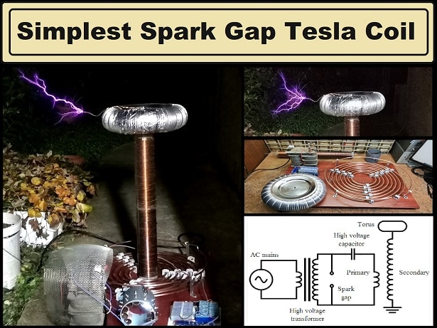
A Solid-State Tesla Coil (SSTC) is a type of Tesla coil that uses solid-state components such as transistors, diodes, and capacitors to generate high-voltage, high-frequency alternating current electricity. This type has several advantages over traditional Tesla coils, which typically use spark gap switches. SSTCs have higher efficiency, the possibility of long-term work, as well as compact dimensions. In fact, compactness and small dimensions are the main characteristics of the Tesla coil, and the construction and operation are described in this project.
SAFETY NOTE: Please do not attempt to recreate the experiments shown in this video unless you are familiar with High Voltage Safety Techniques! Direct Current even above 60V may be lethal, even when the AC supply voltage has been disconnected due to the stored energy in the capacitors.
But despite the small size, the performance is surprisingly good. Another positive feature is its extreme simplicity, so even less experienced self-builders can make it. However, I would like to emphasize that generally making and adjusting any Tesla coil, even though it looks simple, requires adequate knowledge and experience, especially at SSTC, where every small mistake and failed start means burnt components, which are not cheap.
Тhe device consists of only a few components:
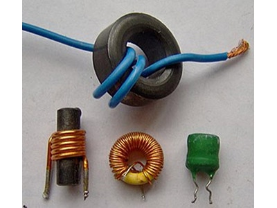
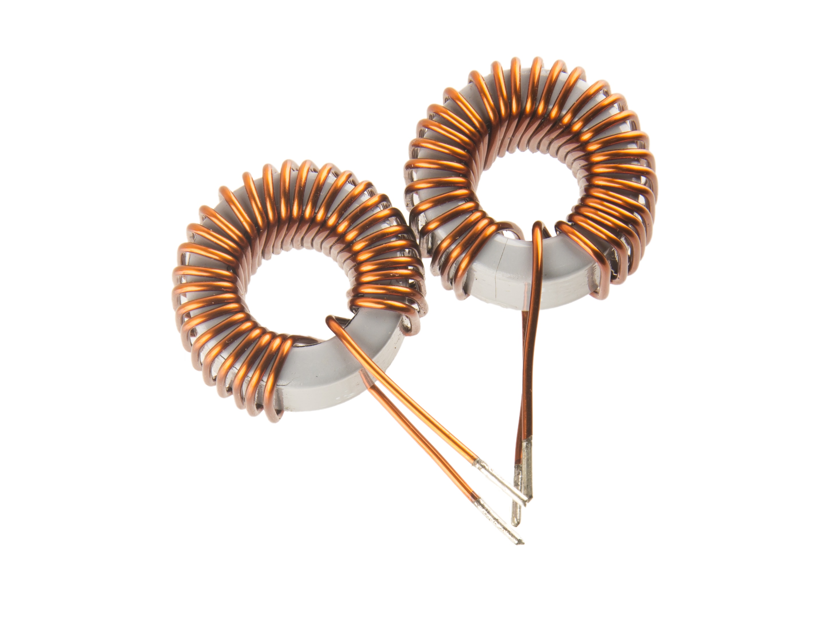
- Primary coil
- Secondary coil
- Top load specifically in the form of a cylinder
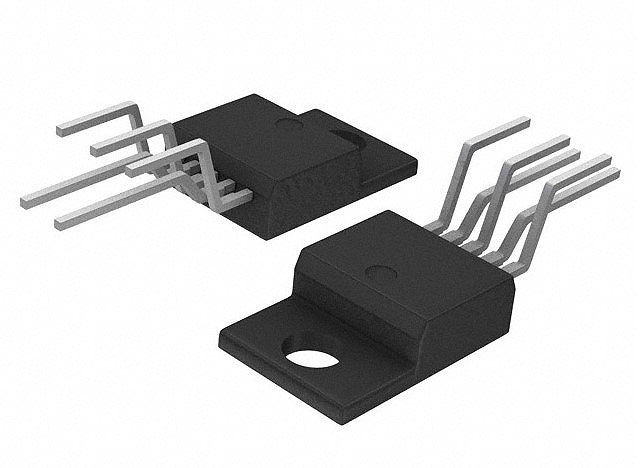
- Powerful Mosfet (currently I use BUZ325, but in the first prototype I used IRfP460 with the same results)
- Heatsink for the mosfet
- diode 5 amp, for example U1540
- Fast diode for Mosfet protection also U1540
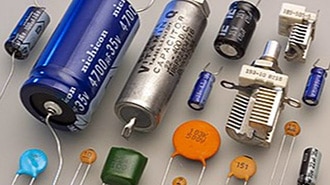
- 1microfarad/250V MKP capacitor
- Potentiometer and Resistor
- Two Zener diodes for 12V
- Fuse 5A
- And a source of alternating voltage, Transformer 50V /3A or more
The primary coil contains 5 windings of 2.5mm copper wire on a plastic body with a diameter of 5cm, and it is desirable to make a lead on each winding to make it easier to adjust the device.
The secondary coil is wound on a plastic body with a diameter of 4cm and contains 520 turns of lacquered copper wire with a diameter of 0.2 mm. The height of the secondary is 12cm. The calculated resonant frequency of this secondary coil together with the top load is about 1.7 MHz.
For a top load I use a small aluminum box.
The power mosfet is specifically an BUZ325, but during testing I successfully used an IRFP460 which is also significantly more powerful. For voltages up to 60 V, IRFP260 can also be used. Of course, the mosfet should be mounted on a massive aluminum heatsink. The rectifying diode should be designed for a current of 5A or more, in this case I use a fast diode of the type U1540. A fuse is mandatory because relatively high voltages and currents are involved. It is very practical to use an automatic fuse as in this particular case. For the sake of constant monitoring of the operation of the circuit as well as the consumption, it is desirable to place a current clamp at the input.
The transformer that I use is taken out of an old defective audio amplifier.
Now a few words about the first turn on and testing of the device. The best option is to use variac if we have it. The variac is actually an autotransformer where we can continuously change the voltage from 0V to the maximum value.
First, we turn on the transformer at a lower voltage so that it outputs about 15V. At start also we need to connect the primary coil with the most turns. (5 in my case). Next, with a fluorescent lamp close to the secondary, we slowly turn the potentiometer to the right. If everything is well connected, at some point the lamp should light up, which is a sign that the circuit has started to oscillate and generates a high voltage at the output.
If this does not happen, we need to reverse the poles of the primary and repeat the same procedure. Now if you connect the lamp again and it doesn't light up, the problem is somewhere in the connection of the components, or some defective component, which is usually the mosfet. If we do not have a variac autotransformer, it is best to start the tests with a transformer with an output voltage of 15 to 20 volts. When we solve the problem, we can start increasing the voltage continuously while keeping an eye on the current clamp, and if the current suddenly increases, we should immediately reduce the input voltage. When we make sure that the Tesla coil is working stably, we gradually decrease one by one turn of the primary until the largest spark is generated.
As you can see on the video, a fully tested and tuned Tesla coil performs amazingly good in real conditions, with rely long spark for this type of simple Tesla coil. Under these conditions, with a 50V power supply, the current was about 2.5 to 3 Amps, which is less than 150 Watts. Then I connect Arduino Staccato controller, the construction of which I described in one of the previous videos.
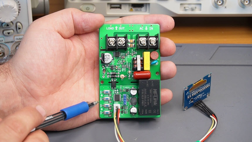
Now, at the same length of the spark, the current did not exceed 0.8A at all and the Tesla coil can work for an unlimited time in these conditions. I managed to reduce the current even further by connecting a simple SCR voltage regulator to the variac input. I will explain how this trick works on a later occasion. And finally, a short conclusion. You can make this miniature and simple Tesla coil in less than a day along with winding the secondary coil which contains only 500 turns. In addition, the final result is surprisingly good with a generated spark with a length of 10cm and more and relatively low consumption, especially when using the Staccato controller. SAFETY NOTE: Please do not attempt to recreate the experiments shown in this video unless you are familiar with High Voltage Safety Techniques! Direct Current even above 60V may be lethal, even when the AC supply voltage has been disconnected due to the stored energy in the capacitors. I have no responsibility for any hazards caused by the circuit. Be very careful. This is a humble request.