Mfr Part # 4469
MLX90640 IR THERM CAMERA 110DEG
Adafruit Industries LLC
License: See Original Project 3D Printing Camera Humidity Temperature Raspberry Pi SBC STEMMA
Courtesy of Adafruit
Guide by Ruiz Brothers and Liz Clark
Overview
Build a thermal imaging camera using a Raspberry Pi, MLX90640 IR camera breakout, and the Raspberry Pi camera module. This project fuses the Raspberry Pi's camera feed with a thermal graphic overlay. A Python script features a graphical interface that allows you to control the overlay's opacity and temperature range, and even take screenshots.
The electronics are housed in a custom designed 3D printed snap fit enclosure. A 1/4-20" mount lets you secure it to just about any tripod compatible mounting system.
This project was inspired by the PitFusion thermal imager for the Raspberry Pi.
Parts
1 x Mini Ball Head
Hardware
3x M3 x 4mm long machine screws
4x M2.5 x 6mm long machine screws
2x M2 x 6mm long machine screws
Circuit Diagram
The diagram below provides a general visual reference for wiring of the components once you get to the Assembly page. This diagram was created using the software package Fritzing.
Adafruit Library for Fritzing
Adafruit uses the Adafruit Fritzing parts library to create circuit diagrams for projects. You can download the library or just grab individual parts. Get the library and parts from GitHub - Adafruit Fritzing Parts.
Wired Connections
Camera Module to Camera Pi via ribbon cable
EYESPI Beret to Pi GPIO Header
STEMMA QT on EYESPIBeret to MLX90640
The Raspberry Pi 4 Model B is powered via 5V 2A USB power supply.
CAD Files
CAD Assembly
The main assembly is available in Fusion 360 and STEP file formats. This includes all of the 3D printed parts and electronic components used in the project. Use the main assembly to create any edits, updates, or modifications.
Download STEP and F360 Source Files
Multicolor Part (Optional)
The top cover can optionally be printed in multiple colors using a multicolor capable 3D printer. The 3MF file contains four objects that can be assigned different colors.
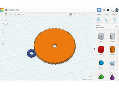
Design Source Files
The project assembly was designed in Fusion 360. Once opened in Fusion 360, It can be exported in different formats like STEP, STL and more.
Electronic components like Adafruit's boards, displays, connectors and more can be downloaded from the Adafruit CAD parts GitHub Repo.
Python Virtual Environment Prep
As Carter writes in his Python Virtual Environment Usage on Raspberry Pi guide:
Starting with the October 10, 2023, Bookworm release of the Raspberry Pi OS, the use of Python Virtual Environments (venv) when pip installing packages is required. No more sudo pip. This will break things and require learning new things. Yeah.
You will need to setup a Python virtual environment (venv) on your Raspberry Pi 5 for this project. Don't worry though! If you follow along with the guide step by step, you'll be just fine.
Python Virtual Environment Usage on Raspberry Pi
By Carter Nelson
Always venv
On the Other Ideas page in the venv guide, there is a tip for having the virtual environment enabled automatically at boot by editing the .bashrc file (sudo nano .bashrc) and adding this line to the bottom:
source home/user/venv/bin/activate
Where venv is the name of your virtual environment. You can take this a step further by adding the alias for running Python scripts as sudo to your .bashrc file as well:
alias gogo='sudo -E env PATH=$PATH python'
You can change gogo to any command you want. This way, every time you boot up your Pi, you'll have your Python venv enabled and you'll be able to use your alias for running Python scripts.
Installing Blinka on Raspberry Pi
CircuitPython libraries and adafruit-blinka will work on any Raspberry Pi board! That means the original 1, the Pi 2, Pi 3, Pi 4, Pi 5, Pi Zero, Pi Zero 2 W, or even the compute modules.
At this time, Blinka requires Python version 3.7 or later, which means you will need to at least be running Raspberry Pi OS Bullseye.
Prerequisite Pi Setup!
In this page we'll assume you've already gotten your Raspberry Pi up and running and can log into the command line
Here's the quick start for people with some experience:
Download the latest Raspberry Pi OS or Raspberry Pi OS Lite to your computer
Burn the OS image to your MicroSD card using your computer
Plug the SD card into the Pi
If you have an HDMI monitor, we recommend connecting it so you can see that the Pi is booting OK
Plug in power to the Pi - you will see the green LED flicker a little. The Pi will reboot while it sets up so wait a good 10 minutes
The Pi Foundation has tons of guides as well
We really really recommend the latest Raspberry Pi OS only. If you have an older Raspberry Pi OS install, run "sudo apt-get update" and "sudo apt-get upgrade" to get the latest OS!
Update Your Pi and Python
Run the standard updates:
sudo apt-get update
sudo apt-get -y upgrade
sudo apt-get install -y python3-pip
and upgrade setuptools:
sudo apt install --upgrade python3-setuptools
You may need to reboot prior to installing Blinka. The raspi-blinka.py script will inform you if it is necessary.
If you are installing in a virtual environment, the installer may not work correctly since it requires sudo. We recommend using pip to manually install it in that case.
Setup Virtual Environment
If you are installing on the Bookworm version of Raspberry Pi OS, you will need to install your python modules in a virtual environment. You can find more information in the Python Virtual Environment Usage on Raspberry Pi guide. To Install and activate the virtual environment, use the following commands:
cd ~
sudo apt install python3-venv
python3 -m venv env --system-site-packages
You will need to activate the virtual environment every time the Pi is rebooted. To activate it:
source env/bin/activate
To deactivate, you can use deactivate but leave it active for now.
Automated Install
We put together a script to easily make sure your Pi is correctly configured and install Blinka. It requires just a few commands to run. Most of it is installing the dependencies.
cd ~
pip3 install --upgrade adafruit-python-shell
wget https://raw.githubusercontent.com/adafruit/Raspberry-Pi-Installer-Scripts/master/raspi-blinka.py
sudo -E env PATH=$PATH python3 raspi-blinka.pyv
If you are installing on an earlier version such as Bullseye of Raspberry Pi OS and not using a Virtual Environment, you can call the script like:
sudo python3 raspi-blinka.py
If you are installing an older version of Raspberry Pi OS, your system default Python is likely Python 2. If so, it will ask to confirm that you want to proceed. Choose yes.
It may take a few minutes to run. When it finishes, it will ask you if you would like to reboot. Choose yes.
Once it reboots, the connection will close. After a couple of minutes, you can reconnect.
Manual Install
If you are having trouble running the automated installation script, you can follow these steps to manually install Blinka.
Enable Interfaces
Run these commands to enable the various interfaces such as I2C and SPI:
sudo raspi-config nonint do_i2c 0
sudo raspi-config nonint do_spi 0
sudo raspi-config nonint do_serial_hw 0
sudo raspi-config nonint do_ssh 0
sudo raspi-config nonint do_camera 0
sudo raspi-config nonint disable_raspi_config_at_boot 0
Install Blinka and Dependencies
Blinka needs a few dependencies installed:
sudo apt-get install -y i2c-tools libgpiod-dev python3-libgpiod
pip3 install --upgrade adafruit-blinka
Raspberry Pi 5 Adjustments
At the moment, RPi.GPIO is installed, which causes issues. Just remove it with the following command:
pip3 uninstall -y RPi.GPIO
Check I2C and SPI
The script will automatically enable I2C and SPI. You can run the following command to verify:
ls /dev/i2c* /dev/spi*
You should see the response
/dev/i2c-1 /dev/spidev0.0 /dev/spidev0.1
Fixing CE0 and CE1 Device or Resource Busy Issue
In order to use the CE0 and CE1 pins in Python, you will need to disable them from OS usage. To do so, check out the Reassigning or Disabling the SPI Chip Enable Lines section of this guide.
Enabling Second SPI
If you are using the main SPI port for a display or something and need another hardware SPI port, you can enable it by adding the line
dtoverlay=spi1-3cs
to the bottom of /boot/config.txt and rebooting. You'll then see the addition of some /dev/spidev1.x devices:
Pi 5 : Cannot determine SOC peripheral base address
comment out this line :
#dtparam=spi=on
Blinka Test
If onewire is enabled, you may need to use another digital input besides D4.
Create a new file called blinkatest.py with nano or your favorite text editor and put the following in:
import board
import digitalio
import busio

print("Hello, blinka!")

# Try to create a Digital input
pin = digitalio.DigitalInOut(board.D4)
print("Digital IO ok!")

# Try to create an I2C device
i2c = busio.I2C(board.SCL, board.SDA)
print("I2C ok!")

# Try to create an SPI device
spi = busio.SPI(board.SCLK, board.MOSI, board.MISO)
print("SPI ok!")

print("done!")
Save it, make sure your virtual environment is activated, and run at the command line with:
python3 blinkatest.py
You should see the following, indicating digital i/o, I2C, and SPI all worked.
Thermal Camera Software
Install the Required Libraries
You will need to install a few libraries to run the thermal camera Python script. In the terminal, enter:
pip install opencv-python adafruit-circuitpython-mlx90640
This installs OpenCV and the Adafruit CircuitPython MLX90640 driver, which is compatible with Blinka.
Download the Project Bundle
Once you've finished setting up your Raspberry Pi with Blinka and the library dependencies, you can access the Python code file by downloading the Project Bundle.
To do this, click on the Download Project Bundle button in the window below. It will download as a zipped folder.
# SPDX-FileCopyrightText: 2025 Liz Clark for Adafruit Industries
#
# SPDX-License-Identifier: MIT
"""
Thermal Camera Overlay for Raspberry Pi 4,
PiCamera 3 and STEMMA MLX90640

Inspired by PitFusion Thermal Imager
"""

import time
import numpy as np
import cv2
import board
import busio
import adafruit_mlx90640
from picamera2 import Picamera2
from PIL import Image

# Temperature range for thermal camera (in Celsius)
MIN_TEMP = 20.0
MAX_TEMP = 35.0

# Thermal overlay opacity (0.0 = invisible, 1.0 = fully opaque)
THERMAL_OPACITY = 0.7

# Display window size
WINDOW_WIDTH = 1280
WINDOW_HEIGHT = 720

# Camera settings
CAMERA_WIDTH = 1280
CAMERA_HEIGHT = 720

SKIP_FRAMES = 2  # Process every Nth frame for thermal
frame_counter = 0

# Thermal camera size
THERMAL_WIDTH = 32
THERMAL_HEIGHT = 24

# Thermal zoom factor (1.7x to compensate for FoV difference)
# Thermal camera FoV: 110°x75°, Pi camera FoV: 66°x41°
# Ratio: 66/110 = 0.6, so we need 1/0.6 = 1.67x zoom
THERMAL_ZOOM = 1.7

# Camera crop settings to compensate for thermal offset
# This crops the camera image to match the thermal coverage area
CAMERA_CROP_LEFT = 65    # Match thermal X offset
CAMERA_CROP_TOP = 85     # Match thermal Y offset
CAMERA_CROP_RIGHT = 0    # No crop on right
CAMERA_CROP_BOTTOM = 0   # No crop on bottom

# Calculate effective camera size after cropping
CAMERA_CROP_WIDTH = CAMERA_WIDTH - CAMERA_CROP_LEFT - CAMERA_CROP_RIGHT
CAMERA_CROP_HEIGHT = CAMERA_HEIGHT - CAMERA_CROP_TOP - CAMERA_CROP_BOTTOM

# ============= SETUP THERMAL CAMERA =============
print("Setting up thermal camera...")
i2c = busio.I2C(board.SCL, board.SDA)
mlx = adafruit_mlx90640.MLX90640(i2c)
mlx.refresh_rate = adafruit_mlx90640.RefreshRate.REFRESH_4_HZ

# Create array to hold thermal data
thermal_frame = np.zeros(768, dtype=np.float32)

# ============= SETUP REGULAR CAMERA =============
print("Setting up Pi camera...")
picam2 = Picamera2()
camera_config = picam2.create_preview_configuration(
    main={"size": (CAMERA_WIDTH, CAMERA_HEIGHT), "format": "RGB888"},
    buffer_count=2,  # Reduce buffer count for lower latency
    queue=False  # Don't queue frames
)
picam2.configure(camera_config)
picam2.start()
picam2.set_controls({"ExposureTime": 20000, "AnalogueGain": 1.0})
time.sleep(2)

# ============= CREATE THERMAL COLORMAP =============
def create_thermal_colormap():
    """Create a colormap for thermal visualization"""
    # Define color points (blue -> cyan -> green -> yellow -> orange -> red)
    colors = np.array([
        [0, 0, 64],       # Dark blue (cold)
        [0, 0, 255],      # Blue
        [0, 255, 255],    # Cyan
        [0, 255, 0],      # Green
        [255, 255, 0],    # Yellow
        [255, 128, 0],    # Orange
        [255, 0, 0],      # Red (hot)
    ], dtype=np.uint8)

    # Create smooth gradient between colors
    colormap = np.zeros((256, 3), dtype=np.uint8)
    positions = np.linspace(0, len(colors)-1, 256)

    for i in range(256):
        pos = positions[i]
        idx = int(pos)
        frac = pos - idx

        if idx >= len(colors) - 1:
            colormap[i] = colors[-1]
        else:
            colormap[i] = (1 - frac) * colors[idx] + frac * colors[idx + 1]

    colormap = colormap[::-1]  # Reverse the colormap
    return colormap
the_colormap = create_thermal_colormap()

# ============= HELPER FUNCTIONS =============
def process_thermal_frame(thermal_data, colormap):
    """Convert thermal data to colored image"""
    # Calculate temperature statistics
    min_temp = np.min(thermal_data)
    max_temp = np.max(thermal_data)
    avg_temp = np.mean(thermal_data)
    if min_temp < -100:
        min_temp = MIN_TEMP
        avg_temp = (MIN_TEMP + MAX_TEMP) / 2

    # Normalize temperature data to 0-255 range
    normalized = np.clip(
        (thermal_data - MIN_TEMP) / (MAX_TEMP - MIN_TEMP) * 255,
        0, 255
    ).astype(np.uint8)

    # Apply colormap
    colored = colormap[normalized]

    # Reshape to 2D image (24x32x3)
    thermal_image = colored.reshape(THERMAL_HEIGHT, THERMAL_WIDTH, 3)

    # Flip horizontally to match camera view
    thermal_image = np.fliplr(thermal_image)

    # Scale up to camera size using PIL for smooth interpolation
    pil_thermal = Image.fromarray(thermal_image)

    # Apply zoom by scaling to a larger size than the camera
    scaled_width = int(CAMERA_WIDTH * THERMAL_ZOOM)
    scaled_height = int(CAMERA_HEIGHT * THERMAL_ZOOM)
    pil_thermal = pil_thermal.resize((scaled_width, scaled_height), Image.BICUBIC)

    # Crop the center to match camera size (this creates the zoom effect)
    thermal_array = np.array(pil_thermal)
    crop_x = (scaled_width - CAMERA_WIDTH) // 2
    crop_y = (scaled_height - CAMERA_HEIGHT) // 2
    thermal_cropped = thermal_array[crop_y:crop_y+CAMERA_HEIGHT, crop_x:crop_x+CAMERA_WIDTH]

    return thermal_cropped, min_temp, max_temp, avg_temp

def blend_images(camera_image, thermal_image, opacity):
    """Blend camera and thermal images with position offset"""
    # Create a canvas the same size as the camera image
    canvas = camera_image.copy()

    # Calculate position with offset
    x_offset = 0
    y_offset = 0

    # Ensure the thermal image fits within bounds
    x_start = max(0, x_offset)
    y_start = max(0, y_offset)
    x_end = min(camera_image.shape[1], x_offset + thermal_image.shape[1])
    y_end = min(camera_image.shape[0], y_offset + thermal_image.shape[0])

    # Calculate the corresponding region in the thermal image
    thermal_x_start = max(0, -x_offset)
    thermal_y_start = max(0, -y_offset)
    thermal_x_end = thermal_x_start + (x_end - x_start)
    thermal_y_end = thermal_y_start + (y_end - y_start)

    # Blend only the overlapping region
    if x_end > x_start and y_end > y_start:
        canvas[y_start:y_end, x_start:x_end] = (
            canvas[y_start:y_end, x_start:x_end] * (1 - opacity) +
            thermal_image[thermal_y_start:thermal_y_end, thermal_x_start:thermal_x_end] * opacity
        )

    return canvas.astype(np.uint8)

def add_temperature_scale(image, colormap):
    """Add temperature scale bar to the image"""
    # Create scale bar
    scale_height = 20
    scale_width = 200
    scale_x = image.shape[1] - scale_width - 20
    scale_y = 90  # Moved down to make room for buttons

    # Draw temperature gradient
    for i in range(scale_width):
        temp_normalized = i / scale_width
        color_idx = int(temp_normalized * 255)
        color = colormap[color_idx]
        cv2.line(image,
                 (scale_x + i, scale_y),
                 (scale_x + i, scale_y + scale_height),
                 color.tolist(), 1)

    # Add temperature labels
    cv2.putText(image, f"{MIN_TEMP:.0f}C",
                (scale_x - 35, scale_y + 15),
                cv2.FONT_HERSHEY_SIMPLEX, 0.5, (255, 255, 255), 1)
    cv2.putText(image, f"{MAX_TEMP:.0f}C",
                (scale_x + scale_width + 5, scale_y + 15),
                cv2.FONT_HERSHEY_SIMPLEX, 0.5, (255, 255, 255), 1)

    # Draw border around scale
    cv2.rectangle(image,
                  (scale_x - 1, scale_y - 1),
                  (scale_x + scale_width + 1, scale_y + scale_height + 1),
                  (255, 255, 255), 1)

# ============= MAIN LOOP =============
print("Starting thermal camera overlay...")
print("Use Up/Down keys to increase/decrease max temp")
print("Use Left/Right keys to increase/decrease min temp")
print("Use +/- keys to increase/decrease overlay opacity")
print("Use Q key to exit")

cv2.namedWindow('Thermal Overlay', cv2.WINDOW_NORMAL)
cv2.resizeWindow('Thermal Overlay', WINDOW_WIDTH, WINDOW_HEIGHT)

# Temperature statistics
temp_stats = {"min": 0, "max": 0, "avg": 0}
last_thermal_colored = None

try:
    while True:

        # Read thermal data (only every SKIP_FRAMES frames)
        if frame_counter % SKIP_FRAMES == 0:
            try:
                mlx.getFrame(thermal_frame)
                # Process thermal data to colored image
                last_thermal_colored, temp_stats["min"], temp_stats["max"], temp_stats["avg"] = process_thermal_frame(thermal_frame, the_colormap) # pylint: disable=line-too-long
            except Exception as e: # pylint: disable=broad-except
                print(f"Thermal read error: {e}")

        frame_counter += 1

        # Use the last processed thermal frame
        if last_thermal_colored is not None:
            thermal_colored = last_thermal_colored
        else:
            # Create a blank thermal image if we don't have one yet
            thermal_colored = np.zeros((CAMERA_HEIGHT, CAMERA_WIDTH, 3), dtype=np.uint8)

        # Capture camera frame
        camera_frame = picam2.capture_array()

        # Crop the camera frame to match thermal coverage area
        camera_cropped = camera_frame[
            CAMERA_CROP_TOP:CAMERA_HEIGHT-CAMERA_CROP_BOTTOM,
            CAMERA_CROP_LEFT:CAMERA_WIDTH-CAMERA_CROP_RIGHT
        ]

        # Resize cropped camera back to full display size
        camera_resized = cv2.resize(camera_cropped, (CAMERA_WIDTH, CAMERA_HEIGHT),
                                                   interpolation=cv2.INTER_LINEAR)

        # Blend camera and thermal images (now both are aligned)
        overlay_image = blend_images(camera_resized, thermal_colored, THERMAL_OPACITY)

        # Add temperature scale
        add_temperature_scale(overlay_image, the_colormap)

        # Add status text with temperature statistics and FPS
        status_text = f"Range: {MIN_TEMP:.0f}-{MAX_TEMP:.0f}C | Opacity: {THERMAL_OPACITY:.1f} | "
        status_text += f"Min: {temp_stats['min']:.1f}C | Max: {temp_stats['max']:.1f}C | Avg: {temp_stats['avg']:.1f}C | "  # pylint: disable=line-too-long
        cv2.putText(overlay_image, status_text,
                    (10, overlay_image.shape[0] - 10),
                    cv2.FONT_HERSHEY_SIMPLEX, 0.6, (255, 255, 255), 2)

        # Display the image
        cv2.imshow('Thermal Overlay', overlay_image)

        # Check if window was closed
        if cv2.getWindowProperty('Thermal Overlay', cv2.WND_PROP_VISIBLE) < 1:
            break

        key_action = cv2.waitKey(1) & 0xFF
        if key_action == ord('q'):
            raise KeyboardInterrupt
        if key_action == 82:
            MAX_TEMP = min(MAX_TEMP + 1, 100)
            print(f"Max temp: {MAX_TEMP:.1f}C")
        elif key_action == 84:
            MAX_TEMP = max(MAX_TEMP - 1, MIN_TEMP + 1)
            print(f"Max temp: {MAX_TEMP:.1f}C")
        elif key_action == 81:
            MIN_TEMP = max(MIN_TEMP - 1, -20)
            print(f"Min temp: {MIN_TEMP:.1f}C")
        elif key_action == 83:
            MIN_TEMP = min(MIN_TEMP + 1, MAX_TEMP - 1)
            print(f"Min temp: {MIN_TEMP:.1f}C")
        elif key_action == ord('+'):
            THERMAL_OPACITY = min(THERMAL_OPACITY + 0.1, 1.0)
            print(f"Opacity: {THERMAL_OPACITY:.1f}")
        elif key_action == ord('-'):
            THERMAL_OPACITY = max(THERMAL_OPACITY - 0.1, 0.0)
            print(f"Opacity: {THERMAL_OPACITY:.1f}")
        elif key_action == ord('z'):
            THERMAL_OPACITY = not THERMAL_OPACITY
            print(f"Opacity: {THERMAL_OPACITY:.1f}")

except KeyboardInterrupt:
    print("\nShutting down...")

finally:
    print("Cleaning up...")
    cv2.destroyAllWindows()
    cv2.waitKey(1)
    picam2.stop()
Run the Script
After downloading the Project Bundle, move the folder to your /home/user directory. Then, unzip the folder by right-clicking on the folder in the File Manager and selecting Extract or with your preferred command line tool. Keep the following file in the /home/user directory:
code.py
To run code.py from the terminal in your Python virtual environment, you'll use this line in the terminal:
sudo -E env PATH=$PATH python code.py
If you created an alias for running Python scripts within your virtual environment, as described in this section of the virtual environment setup page, you can use your alias to run the script instead:
gogo code.py
How the Code Works
The code setups up a camera preview from the Raspberry Pi Camera. The data from the MLX90640 is formed into an array of colors that are overlayed on top of the camera preview. These two feeds are piped to an OpenCV window, which has built-in support for zooming and saving images. You can use keyboard keys to affect different parameters:
Maximum temperature in overlay: up and down arrow keys
Minimum temperature in overlay: left and right arrow keys
Temperature overlay opacity: + and - keys
Exit program: Q key
Assembly
Connect Camera to Pi
Use the included ribbon cable to connect the camera module to the Raspberry Pi.
Reference the assembly photo for connecting the ribbon cable in the correct orientation.
Connect STEMMA QT
Use the STEMMA QT cable to connect the MLX90604 to the EYESPI Beret.
Tripod Screw Insert (Optional)
Insert the 3/8" to 1/4" adapter to the tripod mount if you'd like to secure the 3D printed case to a tripod or the 3D printed base.
Install Tripod Mount
Orient the tripod mount with the bottom half of the case with the three mounting holes lined up.
Insert and fasten three M3 x 4mm machine screws to secure the parts together.
Make sure the micro-SD card is NOT in the Pi's card slot before fitting into it the case.
Install Raspberry Pi
Make sure the micro-SD card is NOT in the Pi's card slot before fitting into it the case.
Orient the Raspberry Pi with the bottom half of the 3D printed case so the various connectors are lined up with the port holes.
Insert the Raspberry Pi into the half with the mounting holes lined up.
Secure Raspberry Pi
Use a minimum of two M2.5 x 6mm long machine screws to secure the Raspberry Pi to the bottom half of the case.
Secure Raspberry Pi Camera
Place the camera module onto the matching set of stand offs on the top half of the 3D printed case.
Use two M2 x 6mm long screws to secure the camera module to the top half of the case.
Secure MLX90604
Place the MLX90604 breakout onto the matching set of standoffs on the top half of the case.
Use two M2.5 x 6mm long machine screws to secure the PCB to the top half of the case.
Install EYESPI Beret
Orient the EYESPI Beret with the 2x20 GPIO header on the Raspberry Pi.
Carefully seat the Beret onto the GPIO header with all of the going into the socket header pins.
Case Closed
Orient the two halves of the case so they're matching correctly.
Carefully adjust the camera's cables so they're neatly fitted inside the case.
Firmly press the two halves together so they snap fit closed.
Install SD Card
Insert the SD card into the micro-SD card slot.
Install Base (Optional)
Line up the hole in the 3D printed base with the tripod screw insert.
Use a 1/4"-20 tripod screw to secure the two parts together.
Final Build
Congratulation on your build! Reference the software page to run the Python script.
Usage
Thermal Overlay
The overlay window features on-screen text on the bottom of the image that displays settings including temperature range, overlay opacity, and average temperature being read by the sensor.
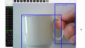
Tool Bar
We're using OpenCV for this project because it has a built-in toolbar at the top of the app window. This toolbar has buttons for zooming in and out and saving images with the overlay. When you save an image, it is stored in the same directory where the script is saved.
Keyboard Controls
The following keyboard keys can be used to quickly adjust settings.
Up Arrow - Increases the maximum temperature range
Down Arrow - Decreases the maximum temperature range
Left Arrow - Decreases the minimum temperature range
Right Arrow - Increases the minimum temperature range
= Key - Increase the overlay opacity
- Key - Decrease the overlay opacity
Q Key - Stops and exits the script