Mfr Part # SC1631
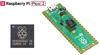
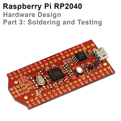
RASPBERRY PI PICO 2 RP2350
Raspberry Pi
License: See Original Project Microcontrollers Raspberry Pi MCU
Courtesy of Pimoroni
Guide by Pimoroni
How fast can RP2350 really go? Mike starts his Christmas holidays with a deep dive into Pico 2 overclocking, with the assistance of a seasonally appropriate amount of dry ice ❄️
A couple of years ago Raspberry Pi posted about overclocking a regular Pico to a ridiculous degree - achieving a 1 GHz overclock and (briefly) boosting the performance of the Pico above the original Pi.
Picos overclock very well, and the original Raspberry Pi Pico will normally run at over 400MHz if given a 1.3V core voltage. On the RP2040 that is as far as you can easily go because the on-board voltage regulator is limited to supplying a maximum of 1.3V.
When I first got my hands on the RP2350 datasheet, one thing I noticed rather quickly was that the voltage regulator could have the voltage limit disabled, so that voltages above 1.3V could be requested. And once I got a Pico 2, I was intrigued to see how it would behave at higher core voltage (and whether the magic smoke would come out if I raised the voltage too high!)
Initial experiments
Using this MicroPython script I was able to request different voltages from the regulator. To find out how fast the RP2350 would clock at a given voltage I ran a simple test that computed 100 factorial and checked the answer was correct, and then incremented the clock speed and continued until it stopped working.
I then did a more rigorous test using the MicroPython performance benchmark to find out whether things were stable. Generally, I had to back off the CPU clock by 20MHz or so in order for the performance benchmark to run multiple times cleanly, compared to how fast it would pass the very simple 100! test. I live bleated (that's what we're calling Bluesky posts for now) my experimentation and some details about the RP2350 as I was doing this.
Voltage, max stable clock speed and temperature for those initial tests was as follows:
This was the first time I'd really felt an RP2 chip getting hot - RP2040s running at 400 MHz or so and 1.3V only get a little warm.
Adding some cooling
To combat the heat issue, I added a tiny heatsink to the RP2350 on the Pico 2, and set up a small PC fan pointing at it to give good airflow. I again live bleated the experiment, pushing the RP2350 to higher voltages and clock speeds:
I'll admit that I was rather concerned going above 2.0V - while the on-board regulator provides 0.05V or 0.1V increments up to 2.0V, the next step up from 2.0V is 2.35V. This seemed like it was getting a long way above the stock 1.1V core voltage, and I thought the danger of cooking the RP2350 was rising.
However, it turned out the performance gain from 2.0 to 2.35V wasn't as much as would be expected, and on further investigation the voltage that the voltage regulator was supplying didn't actually make it above about 2.2V - the on-board regulator isn't able to provide enough current to run the RP2350 at these high voltages.
Test Point 7
So, how did I find out that the supplied voltage wasn't as high as requested? It turns out the Pico 2, rather handily, has a test point on the back that allows you to measure the core voltage. It was therefore very easy to probe it with my multimeter and see the voltage being delivered didn't match up to the requested voltage.
But if you can probe the voltage here, it would also be straightforward to inject a voltage externally. That would mean we could use a bench power supply to provide as much voltage and current as the Pico 2 could take!
Taking it further
A plan forms
I'd been chatting to the folks at Pimoroni about these experiments, whilst helping them with the Presto firmware and other bits and pieces. Niko from the Pimoroni team suggested, perhaps jokingly, that we should try a Liquid Nitrogen overclock.
I'd arranged to pop in to visit Pimoroni HQ at the start of my Christmas break, so we wondered if it might be possible to give this a try. However, LN2 is a little tricky to handle and not totally straightforward to acquire. I was also worried that we could have problems with the soldering, PCB, or connections to the Pico cracking under the extreme cold of LN2.
Solid CO2 (AKA dry ice) on the other hand, is relatively easy to acquire and requires only fairly basic safety precautions. It should allow cooling of the Pico 2 to around -80C, which seemed like it would be enough to give a decent speed boost. Niko ordered some dry ice and the plan was set.
⚠️ (Editorial note: do not experiment with solid CO2 / dry ice unless you know what you're doing, have considered the problems that carbon dioxide sublimation and things being cooled to -80C can cause and have taken appropriate safety precautions!)
Test setup
I wanted to make sure we were pretty rigorous about the testing - unlike the earlier experiments using the MicroPython performance benchmark, I wanted to get both cores running flat out. Therefore, I decided to use the freely available CoreMark benchmark as the test, as this would report result comparable to other CPUs, and it would check for correct operation and report errors if there were problems.
I also wanted the option of running the Pico from the ring oscillator, as described in the Raspberry Pi article linked at the top. Additionally, we weren't quite sure whether the crystal oscillator frequency might be changed by very low temperatures. Therefore, to measure time accurately I sent a 1MHz clock into the Pico 2 under test, and used a simple PIO program to count the cycles. This allowed us to run from the ring oscillator or crystal and get accurate benchmark results measured using a known good clock.
I also made some other adaptations to Protik Banerji's version of Coremark for RP2040, to:
Compile for RP2350, and get two core operation working
Use a copy to RAM build so we got maximum performance and didn't need to worry about the flash clock divider
Use UART output rather than a USB console to avoid USB interrupts slowing down the test and make it easier to recover from the RP2350 crashing
Print the temperature from the RP2350's on board temperature sensor after each run
Run repeatedly in a loop instead of just once
Add a prompt before the runs start to allow the voltage to be set (or the on-board regulator to be disabled), and the frequency to be set or the ring oscillator to be selected
Add a check for console input after each run, allowing the configuration to be modified, or the pico to be rebooted into DFU mode without having to hit the BOOTSEL button. The latter meant we could update things even if it was difficult to press that button when it was buried in dry ice
I used a version of Álvaro Fernández Rojas' pico-uart-bridge on a Pico W to communicate with the Pico 2 under test. This was modified to provide the 1 MHz reference clock, and also look for lines starting "Temp" or "CoreMark" and send them over WiFi.
Using MicroPython on a PicoVision, and a modified version of the temperature display example, I read the temperature and CoreMark readings from the Pico W and graphed them on a monitor, so we could see what was happening while running the tests (I wrote this part in traditional hacker style entirely in my hotel room the night before going into Pimoroni HQ, using the dodgy hotel WiFi and the TV in the room to test it!)
Getting set up
First up we needed to get all three Picos involved in the setup, and the surrounding hardware working and verified. At first, we had some problems with the WiFi communication, which wasn't implemented in the most reliable way, but that seemed to settle down after some initial hiccups.
We got the test Pico 2 running at 100MHz to establish a baseline. Jon at Pimoroni also pointed out that to make things easier to read it would be better to report a number in MHz instead of the CoreMark score, this was achieved simply by taking the ratio of the CoreMark score at 100MHz to the CoreMark being reported. As the CoreMark was running from internal RAM the score should be entirely linear with frequency.
Let's cool the Pico 2!
Next up we got the Pico 2 I'd been using for all the testing so far, complete with its tiny heatsink, and covered it in dry ice.
We did some initial testing using the internal voltage regulator, and got it stable at 700MHz with ease:
Let's cook the Pico 2!
We wanted to push up to see where the limits were, so we wired up a power supply to test point 7, disabled the onboard voltage regulator and nervously increased the voltage above the maximum of 2.2 V that I had managed before.
Up and up the voltage went, and while we got diminishing returns on the frequency achievable, the magic smoke stayed inside the chip!
Here we got to 800MHz at 2.8V:
We realised our setup here was not ideal, as the ground for the core voltage was going via the Pico W. We measured the voltage at the Pico in the dry ice and it was around 200mV lower than the voltage being supplied, due to the resistance through that long path. With that in mind we pushed the voltage up to 3.3V and even a little higher, but it didn't allow that much more speed - the fastest we got to was 840MHz and that wasn't stable for long, we think due to the RP2350 heating up while drawing around 1A of current!
Despite this abuse the Pico 2 still works just fine!
Ring oscillator experiments
The RP2350 datasheet suggests you can "automatically overclock" using the ring oscillator - the concept is that because the ring oscillator itself changes frequency in line with the core voltage and temperature of the chip, the same ring oscillator setting should be stable across all conditions. This appears very much not to be the case (at least while using the Arm cores - see later).
I had found that (air cooled) using the "TOOHIGH" setting and maximum drive strength the Pico 2 ran ok up to around 1.5V and then failed, with the observed frequency at lower voltages being lower than the maximum that could be run from the crystal oscillator, but then it is going up past the maximum frequency as the voltage increased. I'm not sure why this is. Using a drive strength one notch less for one of the two stages had it stable up to the maximum I had tested air cooled, so this was the initial setting we tried using.
However, as we got the voltage higher, at around 2.6V again the RP2350 would crash when running from the ring oscillator, we tried backing off the drive strength which helped a bit, but ultimately it was difficult to find a setting that would run stably at the highest voltages, while being close to the frequency we'd managed with the crystal. That was a bit unfortunate, given that at frequencies above 800MHz we could only step the frequency from the crystal in increments of 12MHz.
Finding a better Pico 2
The Pico 2 that we were using was just the first one I had bought, with no selection based on whether it was a particularly good one for overclocking. Pimoroni rustled up 7 Pico 2s for me to test to try and find one that might overclock the best.
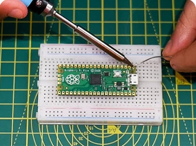
I quickly ran the MicroPython frequency search test (linked near the top) on all of them, finding that at 1.1V they would max out at between 316 and 336MHz. Mark from Pimoroni soldered up the two best ones for further testing. We soldered a few more pins this time to get access to another ground, so the core voltage supply didn't go via the Pico W.
How fast can we go?
Despite being the fastest at 1.1V, the first Pico 2 we tested wasn't that much better than the initial one. We were briefly able to run it at 850MHz at 3.05V, but it wasn't stable. (This is 850MHz measured by dividing the CoreMark, we requested 852MHz, but it seems got slightly less due to the crystal being cold or some other effects of the high core voltage). Going higher than 3.05V seemed to actually make it less stable, so this seemed to be the limit. At 840MHz requested frequency it ran for a couple of minutes, but we saw errors reported from the CoreMark so there must have been errors running some instructions.
Thinking that a lot of the problem in getting faster was just the chip warming up too fast, we looked for a larger thermal mass to try and keep it cooler for longer. Paul produced a big chunk of copper, significantly larger than the Pico 2 itself, which seemed promising.
We tried attaching this to the Pico 2 with a couple of thermal pads, but it seems they didn't provide great thermal conductivity at these low temperatures, because the results were actually worse with this than without any heatsink at all! That was a shame - maybe we should have tried just getting direct contact of the copper on top of the chip, but we were worried about shorts.
We switched over to the other Pico 2 and attached a heatsink designed for the BCM2712 on the Pi 5 to it. That got better results - obviously, the simple test at 1.1V room temperature doesn't account for everything! This one would briefly manage 864MHz requested (reported 860.7MHz), and would run stable at 840MHz for some time, with no errors. The best so far!
Testing the RISC-V cores
The RP2350 is an interesting chip, with two RISC-V cores in addition to the two more established ARM cores. Mark had reminded me that we should try the RISC-V cores for comparison, and I got the image built for them - this is pretty simple to do, you just need to install the RISC-V version of gcc and change the PICO_PLATFORM setting to rp2350-riscv.
I found that CoreMark actually gave a slightly higher performance per MHz using the RISC-V cores - just under 5% faster. So, if you have an integer-only use for the RP2350 it is definitely worth checking if the RISC-V cores might give better performance!
Adjusting the PicoVision monitor for the CoreMark per MHz, we got the same Pico 2 running again.
Maximum speed
Ramping the voltage up again running off the ring oscillator, with the drive strength one notch off maximum on one of the two stages, this time we found it didn't crash as the voltage increased, until we got to around 3.0V. That meant that at around 2.95V we had a stable overclock of 820-840MHz running off the ring oscillator (with the fluctuation in frequency due to temperature).
Switching over to the crystal, with 3.05V we got 861.6MHz (864MHz requested) running cleanly, and it even ran for nearly a minute at 873.5MHz before crashing. We had no luck trying to get a requested frequency of 888MHz to run.
So, the top speed we managed was 873.5MHz, though when we tried this again the Pico refused to start at 3.05V, so I guess we were beginning to cause some damage with the high voltage.
For a final test we left it running on the ring oscillator at 2.95V, and it ran for around 10 minutes before we let it get a little too warm (up to around -20C).
Conclusions
Firstly, the RP2350 and Pico 2 is incredibly hardy. Despite the cold temperatures, some accidental shorting due to moisture when running it while cooling and extremely high core voltages, none of the 3 Pico 2s we were playing with are dead - and I don't think there's any way you would be able to tell that they had been through this treatment.
Above 700MHz the extra performance you get ramping up the voltage gives diminishing returns. This maybe because we just weren't able to keep the chip cool enough - just packing dry ice around it, it becomes difficult to carry enough heat away. Liquid nitrogen might be interesting to experiment with to go further.
Given this experimentation, it seems around 1.6V from the voltage regulator should easily allow a 500MHz or slightly faster overclock without needing any additional cooling and likely without really causing much damage to the Pico - it might be interesting to run a Pico 2 loaded like that for a few days and see if anything bad happens.
Playing with dry ice is fun! If we get a chance to do this again, we should also try overclocking a Pi 5, and see if we could get a speed record there. Although that could be rather more expensive - the great thing about using Pico 2 for this, is that at under £5 per board you can treat them with reckless abandon - after all, they each cost less than a pint of beer!
That's all folks!