Mfr Part # 18430
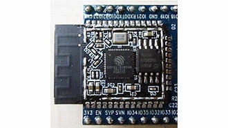
MICROMOD BT WIFI FUNCTION ESP32
SparkFun Electronics
License: See Original Project Wifi Wireless Arduino ESP32 MicroMod
Courtesy of SparkFun
Guide by bboyho, Elias The Sparkiest
Introduction
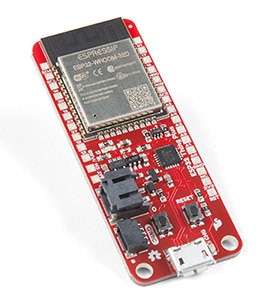
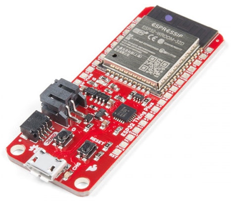
The SparkFun MicroMod ESP32 Function Board adds additional wireless options to MicroMod Processor Boards that do not have that capability. This special function board acts as a coprocessor that takes advantage of Espressif's ESP32 WROOM to add WiFi and Bluetooth® to your applications.
Required Materials
To follow along with this tutorial, you will need the following materials at a minimum. You may not need everything though depending on what you have. Add it to your cart, read through the guide, and adjust the cart, as necessary.
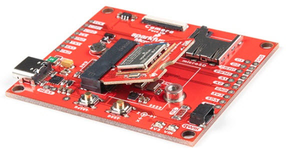
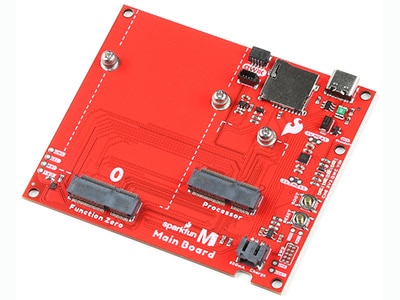
MicroMod Main Board
To hold the processor board and function board, you will need one Main board. Depending on your application, you may choose to have one or two additional function boards.
MicroMod Processor Board
There are a variety of MicroMod Processor Boards available to choose from. You will probably want to avoid having the same Processor and Function Board since there is an ESP32 on both types of boards.
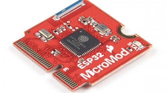
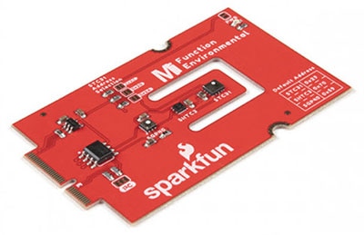
MicroMod Function Board
To add additional functionality to your Processor Board, you'll want to include one or two function boards when connecting them to the Main Board.
Tools
You will need a screwdriver to secure the Processor and Function boards.
Suggested Reading
If you aren't familiar with the MicroMod ecosystem, we recommend reading here for an overview.
If you aren’t familiar with the following concepts, we also recommend checking out a few of these tutorials before continuing. Make sure to check the respective hookup guides for your processor board and function board to ensure that you are installing the correct USB-to-serial converter. You may also need to follow additional instructions that are not outlined in this tutorial to install the appropriate software.
What is an Arduino? What is this 'Arduino' thing anyway? This tutorial dives into what an Arduino is and along with Arduino projects and widgets.
Installing Arduino IDE: A step-by-step guide to installing and testing the Arduino software on Windows, Mac, and Linux.
How to Install CH340 Drivers: How to install CH340 drivers (if you need them) on Windows, Mac OS X, and Linux.
Getting Started with MicroMod: Dive into the world of MicroMod - a compact interface to connect a microcontroller to various peripherals via the M.2 Connector!
Hardware Overview
ESP32
The MicroMod WiFi Function Board includes the ESP32-WROOM module with AT command firmware. The module can be accessed through the serial UART pins.
USB
Note: The CP2101X is powered through the Main Board's VIN pin. Make sure to connect a second USB cable to the Main Board.
The board includes a USB Type C connector on the board to update ESP32's firmware. You will need a Main Board and a second USB cable to update the firmware.
Power
To power the board, you will need to apply power to a SparkFun Main Board. Power applied will connect to the Function Board's VIN pin, which will be regulated down for the rest of the board with the AP2112 3.3V/600mA voltage regulator. Users can control the 3.3V voltage regulator using a Processor Board's I/O pin. For more information, check out the MicroMod Main Board Examples to toggle the pin.
CP2102
The board is populated with the CP2102 USB-to-Serial converter to update firmware on the ESP32 through its USB Type C connector. This allows the board to show up as a device on the serial (or COM) port of the computer. You will need a Main Board and a second USB cable to update the firmware.
Reset and Boot Buttons
The reset button allows users to reset the program running on the ESP32 module without unplugging the board. The boot button allows users to manually flash new firmware to the ESP32.
Transistor
The IC next to the USB-to-Serial converter includes two transistors. This is used by the USB-to-Serial Converter to auto-reset the ESP32 when updating its firmware.
EEPROM
The board includes an I2C EEPROM. Unfortunately, this is not available for the user and was meant to hold board specific information.
LED
There is only one LED available which is the PWR LED. The LED lights up to indicate when available for the ESP32 and CP2102 from the 3.3V voltage regulator. You can disable it by cutting the jumper on the back of the board.
Jumpers
Note: If this is your first time working with jumpers, check out the How to Work with Jumper Pads and PCB Traces tutorial for more information.
The following jumpers are included to configure the board.
PWR - By default, the jumper with the label PWR is closed. This jumper connects the 3.3V line and LED. Cutting this jumper will disable the LED.
I2C Pull-up Resistors - By default, this three-way jumper labeled I2C is closed and connects two pull-up resistors to the I2C data lines. If you have many devices on your I2C data lines, then you may consider cutting these two jumpers.
I2C Pull-up Resistor Jumpers
PWR LED Jumper
Hardware Pinout
Depending on your window size, you may need to use the horizontal scroll bar at the bottom of the table to view the additional pin functions. Note that the M.2 connector pins on opposing sides are offset from each other as indicated by the bottom pins where it says (Not Connected)*. There is no connection to pins that have a "-" under the primary function.
MicroMod WiFi Function Board - ESP32 Pinout Table
MicroMod General Processor Pinout Table
MicroMod General Pin Descriptions
Board Dimensions
The board uses the standard MicroMod Function Board size which measures about 1.50"x2.56".
Hardware Hookup
If you have not already, make sure to check out the Getting Started with MicroMod: Hardware Hookup for information on inserting your Processor and Function Boards to the Main Board.
Dive into the world of MicroMod - a compact interface to connect a microcontroller to various peripherals via the M.2 Connector!
Adding a Function Board to the Main Board
We'll assume that you have inserted a Processor Board into the Main Board already. The process is the same for adding a Function Board. The only difference is that you will be adding two screws to hold the Function board down.
Align the Function Board's key into its M.2 connector's socket. Insert the board at an angle (~25°), push down, and tighten one of the screws to hold the board down. Attach the second screw on the other side of the board. Once the board is aligned, tighten both screws fully to secure the board. In this case, we had the WiFi Function Board secured in the M.2 connector socket. Depending on your application, you may have a different Function Board.
If you decide to have two function boards attached to the Main Board - Double, we recommend tightening the screw between the two Function Boards first to hold them down before attaching the remaining screws on either side of the Function Boards. In this case, we had the WiFi Function Board, and the Environmental Function Board secured in the M.2 connector socket. Depending on your application, you may have different function boards.
ESP32 Firmware Update
To update the firmware, you will need to connect the USB C cable to the MicroMod WiFi Function Board (ESP32) to a computer's COM port. An additional Main Board with a second USB C cable is also needed to power the Main Board and MicroMod WiFi Function Board.
Software Installation
Note: This example assumes you are using the latest version of the Arduino IDE on your desktop. If this is your first time using Arduino, please review the following tutorials.
Arduino Board Definitions and Driver
We'll assume that you installed the necessary board files and drivers for your Processor Board. In this case, we used the MicroMod Artemis Processor Board which uses the CH340 USB-to-serial converter. If you are using a Processor Board, make sure to check out its hookup guide for your Processor Board.
Installing Board Definitions in the Arduino IDE
How do I install a custom Arduino board/core? It's easy! This tutorial will go over how to install an Arduino board definition using the Arduino Board Manager. We will also go over manually installing third-party cores, such as the board definitions required for many of the SparkFun development boards.
MicroMod Artemis Processor Board Hookup Guide
Get started with the Artemis MicroMod Processor Board in this tutorial!
How to install CH340 drivers (if you need them) on Windows, Mac OS X, and Linux.
CP2102 Drivers
For users looking to update the AT Command Firmware, you will need to install the separate Silicon Labs CP210X Driver for the WiFi Function Board - ESP32. The latest can be found from Silicon Labs: USB to UART Bridge VCP Driver.
Download Windows VCP Driver (ZIP)
Download Mac OSX VCP Driver (ZIP)
Note: If applicable, make sure you are using the proper driver files for your CPU architecture. This is usually indicated by a folder or file name with "x86" for 32-bit processors or "x64" for 64-bit processors.
Arduino Examples
Example 1: Connecting to WiFi
This example shows you how to send AT commands from your Processor Board to scan and connect to a WiFi Router. Note that this example runs once in the setup() function.
If you have not already, select your Board (in this case the MicroMod Artemis), and associated COM port. Copy and paste the code below in your Arduino IDE. Make sure to modify the SSID (YOUR_NETWORK_HERE) and password (YOUR_PASSWORD_HERE) for your wireless router. Hit the upload button and set the serial monitor to 115200 baud.
const char* newLineCarriageReturn = "\r\n"; // Used at beginning of code to clear out anything in buffer
const char* toSend = "AT+GMR\r\n"; // Check version information.
const char* enableSys = "AT+SYSLOG=1\r\n"; // Enable AT error code prompt
const char* wifiMode = "AT+CWMODE=3\r\n"; // Set the WiFi mode of ESP devices
const char* whatWifi = "AT+CWLAP\r\n"; // List available APs
const char* connectTo = "AT+CWJAP=\"YOUR_NETWORK_HERE\",\"YOUR_PASSWORD_HERE\"\r\n"; // Connect an ESP station to a targeted AP, where YOUR_NETWORK_HERE is your network SSID, and YOUR_PASSWORD_HERE.
const char* wifiInfo = "AT+CWSTATE?\r\n"; // Query the Wi-Fi state and Wi-Fi information
const char* atReset = "AT+RST\r\n"; // Restart module
const char* whatStandard = "AT+CWAPPROTO?\r\n"; // Sets the 802.11 b/g/n protocol standard of SoftAP mode
//const char* sendLight = "AT+HTTPCLIENT=1,3,192.168.1.116/TEMP86"; // Send HTTP Client Request
//String composedMess = "";
//uint8_t powerEnableZero = A1;
//uint8_t powerEnableOne = 34;
void setup() {
// pinMode(powerEnableOne, OUTPUT);
// pinMode(powerEnableZero, OUTPUT);
Serial.begin(115200); //Arduino Serial Monitor
Serial1.begin(115200); //Hardware Serial Port connected to ESP32
//Let user know that we are ready to begin sending AT commands
Serial.println("We up.");
Serial1.write(newLineCarriageReturn);
delay(1000);//wait for ESP32
Serial1.write(toSend);
delay(1000);//wait for ESP32
//check on ESP32 response
while (Serial1.available()) {
Serial.print(char(Serial1.read()));
}
Serial1.write(enableSys);
delay(1000);//wait for ESP32
//check on ESP32 response
while (Serial1.available()) {
Serial.print(char(Serial1.read()));
}
Serial1.write(wifiMode);
delay(2000);//wait for ESP32
//check on ESP32 response
while (Serial1.available()) {
Serial.print(char(Serial1.read()));
}
Serial1.write(whatWifi);
delay(5000);//wait for ESP32
//check on ESP32 response
while (Serial1.available()) {
Serial.print(char(Serial1.read()));
}
Serial1.write(connectTo);
delay(5000);//wait for ESP32
//check on ESP32 response
while (Serial1.available()) {
Serial.print(char(Serial1.read()));
}
Serial1.write(wifiInfo);
delay(5000);//wait for ESP32
//check on ESP32 response
while (Serial1.available()) {
Serial.print(char(Serial1.read()));
}
Serial.println("Done.");
while (1);
delay(2000);
}
void loop()
{
// digitalWrite(powerEnableZero, LOW);
// digitalWrite(powerEnableOne, LOW);
while (1);
}If all goes well, your ESP32 be configured for each AT command. At one point, the ESP32 will see what other wireless routers (if there are any) are in range before connecting to your WiFi router and providing a status on the connection to your network.
Example 2: Serial Passthrough
This example allows you to use your Processor Board as a serial passthrough to send characters to and from the ESP32 and the USB-to-serial converter. This is useful for testing different AT commands from the Arduino Serial Monitor or terminal window.
If you have not already, select your Board (in this case the MicroMod Artemis), and associated COM port. Copy and paste the code below in your Arduino IDE. Hit the upload button and set the serial monitor to 115200 baud.
char val; //init global var for serial characters being sent from ESP32
void setup()
{
Serial.begin(115200); //Set up Serial Monitor
Serial1.begin(115200); //Set up hardware UART to pipe data from the ESP32
}
void loop()
{
if (Serial.available())
{
//If data comes in from Serial Monitor:
//1.) echo the character back to the Serial Monitor
//2.) send it to Hardware UART.
val = Serial.read(); //save character from Arduino's buffer to a variable
//Serial.print(val); //display serial data back on the Arduino's Serial Monitor, disabled this line if using a Terminal Window
Serial1.write(val); //send serial data to Processor Board's Hardware UART
}
if (Serial1.available())
{ // If data comes in from ESP32 connected to hardware UART,
//display it on the Serial Monitor or Terminal Window
Serial.write(Serial1.read());//display serial data received from
}
}Firmware Update
If you decide to update the firmware, make sure to have the ESP32 connected to the Main Board. Then insert a USB cable to the Main Board and the WiFi Function Board.
When updating firmware for the ESP32, you will need to make sure you select the port that the WiFi Function Board is connected on. It should be the port that is connected to the CP2102. In this case, the port was named as Silicon Labs CP210x USB to UART Bridge under COM11 under the Windows Device Manager.
Head over to Espressif's user guide for instructions, tools, and the latest firmware to update the ESP32. You'll want to use the ESP32 factory binary. Depending on your needs, you could download multiple binaries or generate your own for the ESP32.
ReadTheDocs: ESP-AT User Guide - Downloading Guide
Troubleshooting
Not working as expected and need help?
If you need technical assistance and more information on a product that is not working as you expected, we recommend heading on over to the SparkFun Technical Assistance page for some initial troubleshooting.
SparkFun Technical Assistance Page
If you don't find what you need there, the SparkFun Forums: MicroMod are a great place to find and ask for help. If this is your first visit, you'll need to create a Forum Account to search product forums and post questions.
Resources and Going Further
Now that you've successfully got your MicroMod ESP Function Board up and running, it's time to incorporate it into your own project! For more information, check out the resources below:
Datasheet (ESP32-WROOM-32E)