Mfr Part # 3677
ITSY BITSY 32U4 5V 16MHZ EVAL BD
Adafruit Industries LLC
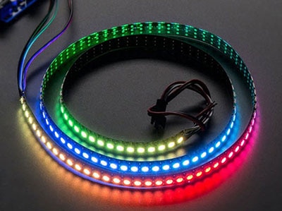
License: See Original Project Addressable LEDs Batteries LED Strips Arduino
I’ve been skiing for over a decade, and I’ve rarely seen people on the mountain with lit-up or modified skis. For some reason, it’s never really taken here in Idaho, and I want to change that. The goal of this project is to create a visual enhancement for skis or snowboards that would work both day and night, and so I came up with an idea for:
Spitfire Skis and Snowboards
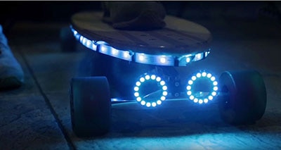
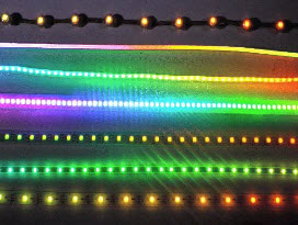
While drilling holes in your winter equipment hasn’t quite caught on as a trend, I’m not the first one to do it, but at least I have the mistakes of my predecessors to show me what not to do! In conjunction with creating a rooster tail effect on the back of my skis, I’m integrating NeoPixel LEDs (Light Emitting Diode) to light up the kicked-up snow and make it look like it’s fire!
I would highly recommend that you read through the whole post before beginning any purchasing or modifying, I’ve included a short section at the end detailing important things that will make this design robust and survive multiple trips without needing repairs.
Design Overview
Here’s a list of everything I used for this design, I will detail the composition below, as well as suggestions for variations. As always refer to the component listing at the bottom to find everything available on DigiKey:
2x Battery Dantona L74A26-2-1-2WX
1x Battery Charger Dantona F074-010-W Charger
2x LDO Diodes Incorporated AZ1084CD
2x Microcontroller Adafruit Itsybitsy 32u4 16Mhz 5V
4x Crimp Connectors (Optional) Molex Quick Connect Female Molex Quick Connect Male
1x Epoxy The type will vary based on the composition of the material you’re adhering to.
1x Silicone Adhesive The type will vary based on the composition of the material you’re adhering to.
2x Decoupling Capacitors, 22uF and 10uF (Electrolytic or Ceramic work fine, if you use Electrolytic remember that they are polarized, the negative side will be ground in all cases in this design)
A drill with an arbitrarily small bit for drilling pilot holes
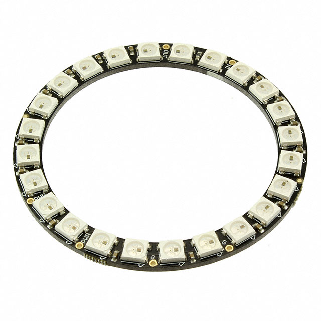
¾in to 1¾in hole cutting bit (with centered guide bit) Size choice will depend on the NeoPixel ring size you choose, any size in this range specifically will work perfectly for the 25 LED NeoPixel ring.
I’ve designed a simple schematic that can be applied to a single ski or snowboard, the idea here is to avoid printing a custom PCB (Printed Circuit Board) since there is only a single IC (Integrated Circuit) in conjunction with the main microcontroller that drives the NeoPixels.
Starting from the left to the right, I’ll be using a 7.4V Battery, Dantona’s L74A26-2-1-2WX was chosen specifically because of its current delivery capabilities, NeoPixels are not rated higher than 5V, and are too current hungry for most low-cost 5V batteries, so we must run this battery directly to an LDO (Low-Dropout Regulator) to bring our voltage down to 5V. We’ll be using an Arduino to control the NeoPixels, and it does have an onboard regulator, but it can’t handle the current that the 24 LED NeoPixel ring pulls, so the best trick here is to just supply them both from the same supply. We’ll lose some efficiency since we’re dropping from 7.4V to 5V, but I challenge you to find a battery closer to 5V, that has a nice recharging system and can deliver a similar amount of current!
In my design I used Diodes Incorporated’s AZ1084CD for my LDO because I had them on hand, they are a little overkill for what we need, so any 5V LDO that can handle up to 1.5-2A should be well in the clear. The amount of current you’ll need will be dependent on the amount of NeoPixels on your ring. I would recommend getting something through-hole rather than my surface mount versions, I had to force them to become through-hole through careful soldering, and if you can skip that step it will save you a headache. You might consider making a custom PCB for this project; I avoided it since we’re only working with a single IC besides the Arduino, but in the future, modifications such as switches, battery indicators, and other fun twists would be much easier to implement through a PCB. Ensure for whatever LDO you use to follow the datasheet’s typical application recommendations, for mine (and for most) you’ll need some sort of decoupling capacitors on the input and output signal.
The Main Brain of our operation is going to be Adafruit’s Itsybitsy 32u4 16Mhz 5V development board. I am super partial to Adafruit’s low-cost Itsybitsy boards because they are super low-power (even their Bluetooth versions) and they can handle quite a bit of stuff in such small packaging.
I used the Arduino IDE to set up this device, since it’s an Adafruit device setting up the IDE and interfacing with it is spectacularly easy. If you’ve never done it before, or need a refresher, there is a super simple guide produced by Adafruit to get everything rolling. Once you’ve done that, install the Adafruit NeoPixel library by clicking on the library bar on the left side. We’ll be using the “Adafruit NeoPixel” library, published by Adafruit. At the time of writing this library has been updated to version 1.12.3.
I ran the verification sketch that the NeoPixel library comes with, and it defaults its connection for data to pin 6, you could use any of the other digital logic pins if you desired, but the sketch I used was called strandtest. (You can find it in the Arduino IDE by clicking File->Examples->Adafruit NeoPixel->strandtest) If you followed everything correctly you should see your device begin to light up as soon as you upload the sketch to your Arduino!
You need to decide on how the electronics will be positioned, the way I see it there are two ways of going about the final hook up, you could either run cables from the NeoPixel ring to your ski or snowboard binding, then solder on one of those quick connect plugs. Then you can run a cable down your snow pants to the connection piece and connect it that way, keeping the Arduino, battery, and LDO in a pocket or something. The alternative is mounting the whole thing on the ski in a project box, which will be more expensive but arguably less likely to get tangled. The decision is yours!
Implementation Steps
#include <Adafruit_NeoPixel.h>
#define LED_PIN 6 // Pin connected to the NeoPixel ring
#define LED_COUNT 24 // Number of LEDs in the NeoPixel ring
Adafruit_NeoPixel strip(LED_COUNT, LED_PIN, NEO_GRB + NEO_KHZ800);
void setup() {
#if defined(__AVR_ATtiny85__) && (F_CPU == 16000000)
clock_prescale_set(clock_div_1);
#endif
strip.begin();
strip.show(); // Initialize all pixels to 'off'
strip.setBrightness(255); // Set brightness
}
void loop() {
fireFlicker(100); // Flicker with randomness
}
// Function to perform fire-like flickering
void fireFlicker(int delayTime) {
for (int i = 0; i < strip.numPixels(); i++) {
// 80% chance for orange, 10% for yellow, 10% for red
int choice = random(0, 10);
if (choice < 6) {
strip.setPixelColor(i, strip.Color(255, 55, 0)); // Orange
} else if (choice == 6) {
strip.setPixelColor(i, strip.Color(255, 100, 0)); // Yellow
} else if (choice == 7) {
strip.setPixelColor(i, strip.Color(255, 120, 0)); // Yellow-ish
} else {
strip.setPixelColor(i, strip.Color(255, 0, 0)); // Red
}
}
strip.show(); // Update the LEDs
delay(delayTime); // Wait before the next update
}
Please note that one of my projects uses crimp connectors for the battery connection, while the other uses JST connectors. I wanted to test both for connectivity, and both work great. Be sure to keep your pins isolated to avoid shorting out the battery!
I chose the hole position on the back of the ski based on two factors, where the ski still lay flat on the ground (the tips bent upwards on the back) and where it was thick enough that I wasn’t worried about it snapping. The closer you are to the bindings, the more snow will likely be scooped up by the hole, and the weaker the ski will be since most skis thin towards the middle, so you’ll have a greater effect at an increased breakage risk. As for the hole size, it will be dependent on the size of your LED ring, if you’re using the same 24 LED NeoPixel ring as me, you can get away with probably a maximum size of 1¾in bit. Smaller will work fine, I wouldn’t go smaller than ¾in though.
These bright LEDs are going to have no problem illuminating snow as we kick it up from the mountain! Legitimately using these bad boys, I’ve had so many comments and people telling me how awesome they look coming down the mountain. There were even a few people genuinely worried I had lit my skis on fire! Since the time of writing this, I've taken these skis up to my local mountain on three separate occasions and skied for over four hours each time without any issues, I even left them on as I drove back down the mountain, and they remained on the whole way until I got home, for me that's over five hours of battery life across some rough terrain without them ever shutting off, even in the cold!
Things I did wrong, so you don't have to
It took me a few prototypes before I got a version robust enough to survive multiple trips. The most common problem that I would experience after getting everything assembled was vibration. I didn’t really think about it at first, but when skiing or snowboarding, the skis and snowboards flex and vibrate a ton, especially if you ride hard, so it’s important that if you’re using a project box to hold the electronics, to adhere things to the bottom and sides of the box to prevent them from moving around. In my first attempt at using these, I didn’t have anything glued down because I figured the solid-core wire I used would be rigid enough. It was not. I ran a single run without the lights on, then when I went to turn them on my Arduino had been obliterated by the weight of the battery on top of it. Now whenever I seal the project boxes up, I have a piece of cloth wrapped around the battery to cushion it and fill up the box so there isn't any room to move around.
The other thing that I would be wary of is cuts to your exposed wires. Luckily, after the first go around, I found that there were scratches in some of the plastic sleeves of the exposed wires connecting to the lights. Skis naturally get crossed sometimes, especially in lift lines, so I covered all the exposed wires with that flexible silicon sealant and that was such a fantastic move. The flexibility of the silicone prevents things from cutting into it, so it cushions the wires from dangerous sharp edges, and is still transparent, so light can still pass through if you want to put it over the NeoPixel LEDs too.
Strengthen your solder joints. The most common point of failure after the second attempt was just the solid core wire breaking where I had it bent a little too sharply. The solid core wire was perfect for the outside of the box going in, acting tough and resistant to movement or impacts, but on the inside the flexibility of stranded wire was important, because the rigidity of the solid core was causing breaks. It makes the electronics a little harder to work with when it’s flexible, but it will last much longer if the connections are good.