Mfr Part # DFR0992-EN
UNIHIKER K10 AI EDUCATIONAL TOOL
DFRobot
License: General Public License Light Arduino ESP32 micro:bit
The other day, I received a shipment with a UNIHIKER K10 development board from DFRobot, which I received as a prize. The device is excellently packaged in a branded box, protected from damage during transportation.
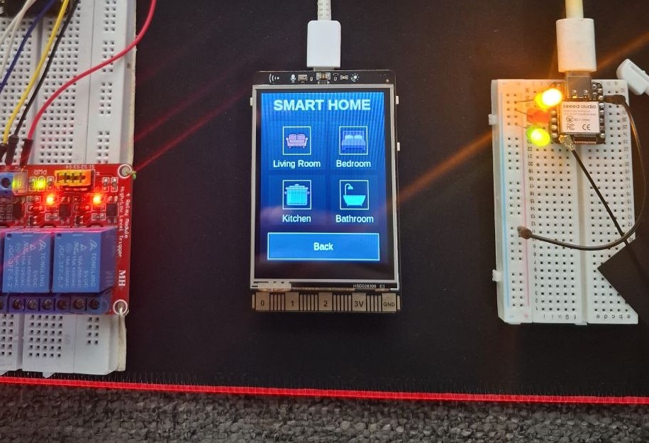
I immediately asked for information because I have no experience with this development board so far. In fact, the device is based on an ESP32-S3 Xtensa LX7 microcontroller and an ILI9341 TFT display with a resolution of 320x240 pixels. The display is protected by a metal frame, and right above it are a light sensor, a temperature and humidity sensor, as well as two microphones for noise reduction. There are two buttons on the side and an edge connector at the bottom for connecting additional modules and sensors. On the back, there is a camera, three I/O connectors, a micro SD slot, a speaker, three RGB LEDs, an accelerometer, and a battery interface.
First, I made a 3D printed case according to the .stl file provided on the manufacturer's website. The case fits perfectly on the back of the PCB and protects the sensitive components. There are openings for the camera, I/O connectors, USB port, and the buttons are functional.
After successful boot-up, K10 runs the factory-built-in programs: Face Detection, voice recognition, Sensor mode, and "View Tutorial" mode, which generates the QR code, and, using your cell phone, you can view the tutorial of K10. By pressing the B button, we move through the menu.
As for software, the supported environments are MindPlus, Arduino IDE, and MicroPython. Basically, the K10 is designed as a device for exploring: AI (artificial intelligence), IoT, and Python Coding. Even all the support from internet groups and communities relates to these areas. My previous experience has only been with Arduino IDE, so I was pleasantly surprised to read that this board supports it. However, I quickly learned that Arduino IDE support is limited to a single library, "unihiker_k10.h".
I even contacted the manufacturer regarding support for other standard Arduino libraries, but the answer was that the SDK for Arduino IDE is under development, and is currently recommended to be used only in conjunction with MindPlus.
So I decided to do some research myself and try to install some kind of program using standard libraries. Actually, it's an ESP32 MCU and an ILI9341 driver-based TFT Display, so it seemed logical to me to start with a project that would use some known library, so I chose Bodmer's TFT_eSPI.
First, I downloaded and carefully studied the Unihiker K10 schematic and the way to connect the microcontroller to the Display.
Based on the data from the schematic, I modified User_Setup.h to match the specific connection. Next, I installed support in Arduino IDE for this development board as follows:
We go to File-> Preferences-> Additional boards manager, and enter the given link:
https://downloadcd.dfrobot.com.cn/UNIHIKER/package_unihiker_index.json
Then, in Tools-> Boards Manager, we write Unihiker, and we install the support for Unihiker from DFRobot.
Now we go to Tools -> Unihiker -> Unihiker K10.
With this, the support for this development board in the Arduino IDE is installed.
Now comes the interesting part, which is testing. Of course, to start with, I tried installing one of the examples included in this library, specifically an analog meter. The example installed successfully without errors, but unfortunately, after rebooting, the display remained black. I went back to the schematic again and discovered that the backlight of the display is controlled by a transistor whose base is connected to a special pin on the I/O expansion chip and not directly to the microcontroller, which theoretically means that there is no chance to programmatically turn on the backlight of the display.
I could probably do it in hardware by directly connecting the ground of the LED pin, but that would be difficult to do, and there was also a chance of damaging the board. I came to the solution by accident, and in the following way:
First, the factory firmware is installed on the board according to the instructions provided on the site. Then, without disconnecting the board from the USB, the indicated example from the TFT-ESPI library is installed, and after uploading, a beautiful analog meter appears on the screen.
I assume that the same procedure works on other display libraries such as Adafruit ILI9341.
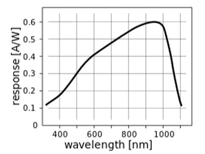
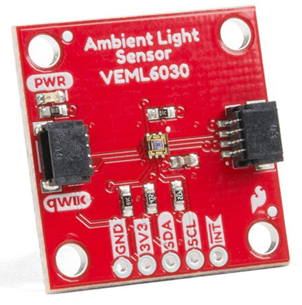
After this, it was logical to try to activate some sensor from the board, and its values would be displayed on the analog meter. I decided on the LTR303 light sensor located just above the display.
In this case, I use the Adafruit library designed for this type of sensor. I took most of the program from the example in the library, which concerns drawing and moving the needle of the analog meter. The other part uses the Adafruit library to read the values received by the sensor. To my surprise, this library also functions quite normally on the K10 development board.
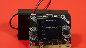
The device is very practical and displays several parameters. The main part is the analog meter, and it displays the relative light intensity received by the sensor on a scale from 0 to 100.
This value is numerically displayed on the lower left part of the instrument. Below the instrument are two important values: the raw value provided by the sensor and the range in which the instrument is currently operating. The value of the light intensity can be easily expressed in Lux units using a simple formula provided by the sensor manufacturer.
The real raw values for the intensity of light from complete darkness to direct sunlight range from 0 to several tens of thousands, so if the entire range were displayed on this scale, the resolution would be extremely low. Therefore, for greater precision and flexibility of the device, I introduced auto-range min-max values, which are based on the light intensity at the moment the device is turned on. If the intensity at a certain moment exceeds the limits of the set range, it will automatically change. Let's see how it looks in reality.
UPDATE:
In the meantime, I found a solution to the problem with the backlight on the display. I also included the library "unihiker_k10.h" and initialized the backlight in the setup. So now the program just needs to be installed on the board, regardless of which program was previously installed. Also, now, after turning off the board from the power supply and turning it back on, the program is activated, along with the backlight turned on.
And finally, a short conclusion. This project demonstrates that despite limited official Arduino support, the Unihiker K10's ESP32-S3 foundation allows determined makers to leverage standard Arduino libraries for creative projects. The successful integration of TFT_eSPI and Adafruit sensor libraries proves this AI-focused board has untapped potential for traditional microcontroller applications.
/*UNIHIKER K10 Light Meter
by mircemk, August 2025
*/

#include <TFT_eSPI.h>
#include <SPI.h>
#include "Adafruit_LTR329_LTR303.h"
#include "unihiker_k10.h"

#define M_SIZE 1.3333
TFT_eSPI tft = TFT_eSPI();
#define TFT_GREY 0x5AEB
#define TFT_LIGHTPINK 0xFDB8
#define TFT_GOLD 0xFEA0
#define TFT_LIGHTGREEN 0x9772
#define TFT_LIGHTSALMON 0xFD0F
#define INFO_PANEL_HEIGHT M_SIZE*30
#define FOOTER_HEIGHT M_SIZE*20  // Height for the version footer

UNIHIKER_K10 k10;
uint8_t      screen_dir=2;

// Light sensor
Adafruit_LTR303 ltr;

// Meter variables
float ltx = 0;
uint16_t osx = M_SIZE*120, osy = M_SIZE*120;
uint32_t updateTime = 0;
int old_analog = -999;

// Light sensor variables
uint16_t minLight = 0;
uint16_t maxLight = 1000;
uint32_t lastSensorRead = 0;
const uint32_t SENSOR_READ_INTERVAL = 100;

void setup(void) {
  Serial.begin(115200);

      k10.begin();
    k10.initScreen(screen_dir);

  if (!ltr.begin()) {
    Serial.println("Couldn't find LTR sensor!");
    while (1) delay(10);
  }

  ltr.setGain(LTR3XX_GAIN_1);
  ltr.setIntegrationTime(LTR3XX_INTEGTIME_50);
  ltr.setMeasurementRate(LTR3XX_MEASRATE_50);

  tft.init();
  tft.setRotation(1);
  tft.fillScreen(TFT_BLACK);
  analogMeter();
  drawInfoPanel(0);
  drawFooter();
  updateTime = millis();
}

void loop() {
  uint16_t visible_plus_ir, infrared;
  bool valid;

  if (millis() - lastSensorRead > SENSOR_READ_INTERVAL) {
    lastSensorRead = millis();

    if (ltr.newDataAvailable()) {
      valid = ltr.readBothChannels(visible_plus_ir, infrared);
      if (valid) {
        if (visible_plus_ir < minLight) minLight = visible_plus_ir;
        if (visible_plus_ir > maxLight) maxLight = visible_plus_ir;

        int mappedValue = map(visible_plus_ir, minLight, maxLight, 0, 100);
        mappedValue = constrain(mappedValue, 0, 100);

        plotNeedle(mappedValue, 10);
        drawInfoPanel(visible_plus_ir);
      }
    }
  }
}

void drawInfoPanel(uint16_t lightValue) {
  // Clear and draw panel
  tft.fillRect(0, M_SIZE*126, M_SIZE*239, INFO_PANEL_HEIGHT, TFT_YELLOW);
  tft.drawRect(0, M_SIZE*126, M_SIZE*239, INFO_PANEL_HEIGHT, TFT_BLACK);

  // Set larger font (Font 4)
  tft.setTextColor(TFT_BLACK, TFT_YELLOW);
  tft.setTextFont(4); // Larger font

  // Format and display text
  char infoText[40];
  snprintf(infoText, sizeof(infoText), "RAW:%-5d  RNG:%d-%d",
           lightValue, minLight, maxLight);

  // Center the text in the panel
  int16_t textWidth = tft.textWidth(infoText, 4);
  int16_t xPos = (M_SIZE*239 - textWidth) / 2;
  tft.setCursor(xPos, M_SIZE*133);
  tft.print(infoText);
}

void drawFooter() {
  // Sky blue footer
  tft.fillRect(0, M_SIZE*126 + INFO_PANEL_HEIGHT, M_SIZE*239, FOOTER_HEIGHT, TFT_CYAN);

  // Centered version text
  tft.setTextColor(TFT_BLACK, TFT_CYAN);
  tft.setTextFont(2);  // Medium-sized font

  const char* versionText = "Light Intensity Meter V1.0 by mircemk";
  int16_t textWidth = tft.textWidth(versionText, 2);
  int16_t xPos = (M_SIZE*239 - textWidth) / 2;
  int16_t yPos = M_SIZE*126 + INFO_PANEL_HEIGHT + (FOOTER_HEIGHT/2 - 8);  // Vertically centered

  tft.setCursor(xPos, yPos);
  tft.print(versionText);
}


// #########################################################################
//  Draw the analogue meter on the screen
// #########################################################################
void analogMeter() {
  // Meter outline
  tft.fillRect(0, 0, M_SIZE*239, M_SIZE*126, TFT_LIGHTSALMON);
  tft.fillRect(5, 3, M_SIZE*230, M_SIZE*119, TFT_WHITE);

  tft.setTextColor(TFT_BLACK);  // Text colour

  // Draw ticks every 5 degrees from -50 to +50 degrees (100 deg. FSD swing)
  for (int i = -50; i < 51; i += 5) {
    // Long scale tick length
    int tl = 15;

    // Coodinates of tick to draw
    float sx = cos((i - 90) * 0.0174532925);
    float sy = sin((i - 90) * 0.0174532925);
    uint16_t x0 = sx * (M_SIZE*100 + tl) + M_SIZE*120;
    uint16_t y0 = sy * (M_SIZE*100 + tl) + M_SIZE*140;
    uint16_t x1 = sx * M_SIZE*100 + M_SIZE*120;
    uint16_t y1 = sy * M_SIZE*100 + M_SIZE*140;

    // Coordinates of next tick for zone fill
    float sx2 = cos((i + 5 - 90) * 0.0174532925);
    float sy2 = sin((i + 5 - 90) * 0.0174532925);
    int x2 = sx2 * (M_SIZE*100 + tl) + M_SIZE*120;
    int y2 = sy2 * (M_SIZE*100 + tl) + M_SIZE*140;
    int x3 = sx2 * M_SIZE*100 + M_SIZE*120;
    int y3 = sy2 * M_SIZE*100 + M_SIZE*140;

    // Green zone limits
    if (i >= 0 && i < 25) {
      tft.fillTriangle(x0, y0, x1, y1, x2, y2, TFT_GREEN);
      tft.fillTriangle(x1, y1, x2, y2, x3, y3, TFT_GREEN);
    }

    // Orange zone limits
    if (i >= 25 && i < 50) {
      tft.fillTriangle(x0, y0, x1, y1, x2, y2, TFT_ORANGE);
      tft.fillTriangle(x1, y1, x2, y2, x3, y3, TFT_ORANGE);
    }

    // Short scale tick length
    if (i % 25 != 0) tl = 8;

    // Recalculate coords incase tick lenght changed
    x0 = sx * (M_SIZE*100 + tl) + M_SIZE*120;
    y0 = sy * (M_SIZE*100 + tl) + M_SIZE*140;
    x1 = sx * M_SIZE*100 + M_SIZE*120;
    y1 = sy * M_SIZE*100 + M_SIZE*140;

    // Draw tick
    tft.drawLine(x0, y0, x1, y1, TFT_BLACK);

    // Check if labels should be drawn, with position tweaks
    if (i % 25 == 0) {
      // Calculate label positions
      x0 = sx * (M_SIZE*100 + tl + 10) + M_SIZE*120;
      y0 = sy * (M_SIZE*100 + tl + 10) + M_SIZE*140;
      switch (i / 25) {
        case -2: tft.drawCentreString("0", x0, y0 - 12, 2); break;
        case -1: tft.drawCentreString("25", x0, y0 - 9, 2); break;
        case 0: tft.drawCentreString("50", x0, y0 - 7, 2); break;
        case 1: tft.drawCentreString("75", x0, y0 - 9, 2); break;
        case 2: tft.drawCentreString("100", x0, y0 - 12, 2); break;
      }
    }

    // Now draw the arc of the scale
    sx = cos((i + 5 - 90) * 0.0174532925);
    sy = sin((i + 5 - 90) * 0.0174532925);
    x0 = sx * M_SIZE*100 + M_SIZE*120;
    y0 = sy * M_SIZE*100 + M_SIZE*140;
    // Draw scale arc, don't draw the last part
    if (i < 50) tft.drawLine(x0, y0, x1, y1, TFT_BLACK);
  }

  tft.drawString("Light", M_SIZE*(5 + 230 - 40), M_SIZE*(119 - 20), 2); // Units at bottom right
  tft.drawCentreString("Light", M_SIZE*120, M_SIZE*70, 4); // Comment out to avoid font 4
  tft.drawRect(5, 3, M_SIZE*230, M_SIZE*119, TFT_BLACK); // Draw bezel line

  plotNeedle(0, 0); // Put meter needle at 0
}

// #########################################################################
// Update needle position
// #########################################################################
void plotNeedle(int value, byte ms_delay) {
  tft.setTextColor(TFT_BLACK, TFT_WHITE);
  char buf[8]; dtostrf(value, 4, 0, buf);
  tft.drawRightString(buf, M_SIZE*40, M_SIZE*(119 - 20), 2);

  if (value < -10) value = -10; // Limit value to emulate needle end stops
  if (value > 110) value = 110;

  // Move the needle until new value reached
  while (!(value == old_analog)) {
    if (old_analog < value) old_analog++;
    else old_analog--;

    if (ms_delay == 0) old_analog = value; // Update immediately if delay is 0

    float sdeg = map(old_analog, -10, 110, -150, -30); // Map value to angle
    // Calcualte tip of needle coords
    float sx = cos(sdeg * 0.0174532925);
    float sy = sin(sdeg * 0.0174532925);

    // Calculate x delta of needle start (does not start at pivot point)
    float tx = tan((sdeg + 90) * 0.0174532925);

    // Erase old needle image
    tft.drawLine(M_SIZE*(120 + 20 * ltx - 1), M_SIZE*(140 - 20), osx - 1, osy, TFT_WHITE);
    tft.drawLine(M_SIZE*(120 + 20 * ltx), M_SIZE*(140 - 20), osx, osy, TFT_WHITE);
    tft.drawLine(M_SIZE*(120 + 20 * ltx + 1), M_SIZE*(140 - 20), osx + 1, osy, TFT_WHITE);

    // Re-plot text under needle
    tft.setTextColor(TFT_BLACK);
    tft.drawCentreString("Light", M_SIZE*120, M_SIZE*70, 4);

    // Store new needle end coords for next erase
    ltx = tx;
    osx = M_SIZE*(sx * 98 + 120);
    osy = M_SIZE*(sy * 98 + 140);

    // Draw the needle in the new postion
    tft.drawLine(M_SIZE*(120 + 20 * ltx - 1), M_SIZE*(140 - 20), osx - 1, osy, TFT_RED);
    tft.drawLine(M_SIZE*(120 + 20 * ltx), M_SIZE*(140 - 20), osx, osy, TFT_MAGENTA);
    tft.drawLine(M_SIZE*(120 + 20 * ltx + 1), M_SIZE*(140 - 20), osx + 1, osy, TFT_RED);

    // Slow needle down slightly as it approaches new postion
    if (abs(old_analog - value) < 10) ms_delay += ms_delay / 5;

    // Wait before next update
    delay(ms_delay);
  }
}