How to Use Arduino 4 Channel Relay Shield Using Visual Programming
2025-07-17 | By Ron Cutts
License: General Public License DC Motor Light Power Supplies Relays Arduino
In this tutorial, we will learn how simple it is to use an Arduino 4-channel Relay Shield to control a 12V light bulb.
In the first example, the light bulb will just blink, and in the second example, we will turn on or off the light bulb using a button, and in the third example, using a remote control.
Watch the video!
Step 1: What You Will Need


Visuino software: Download here
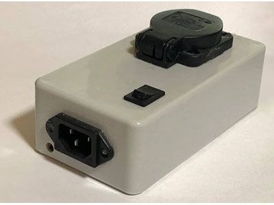
Remote Control - 433 MHz RF module (Optional)
Button (Optional)
1K ohm resistor (Optional)
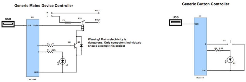
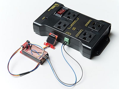
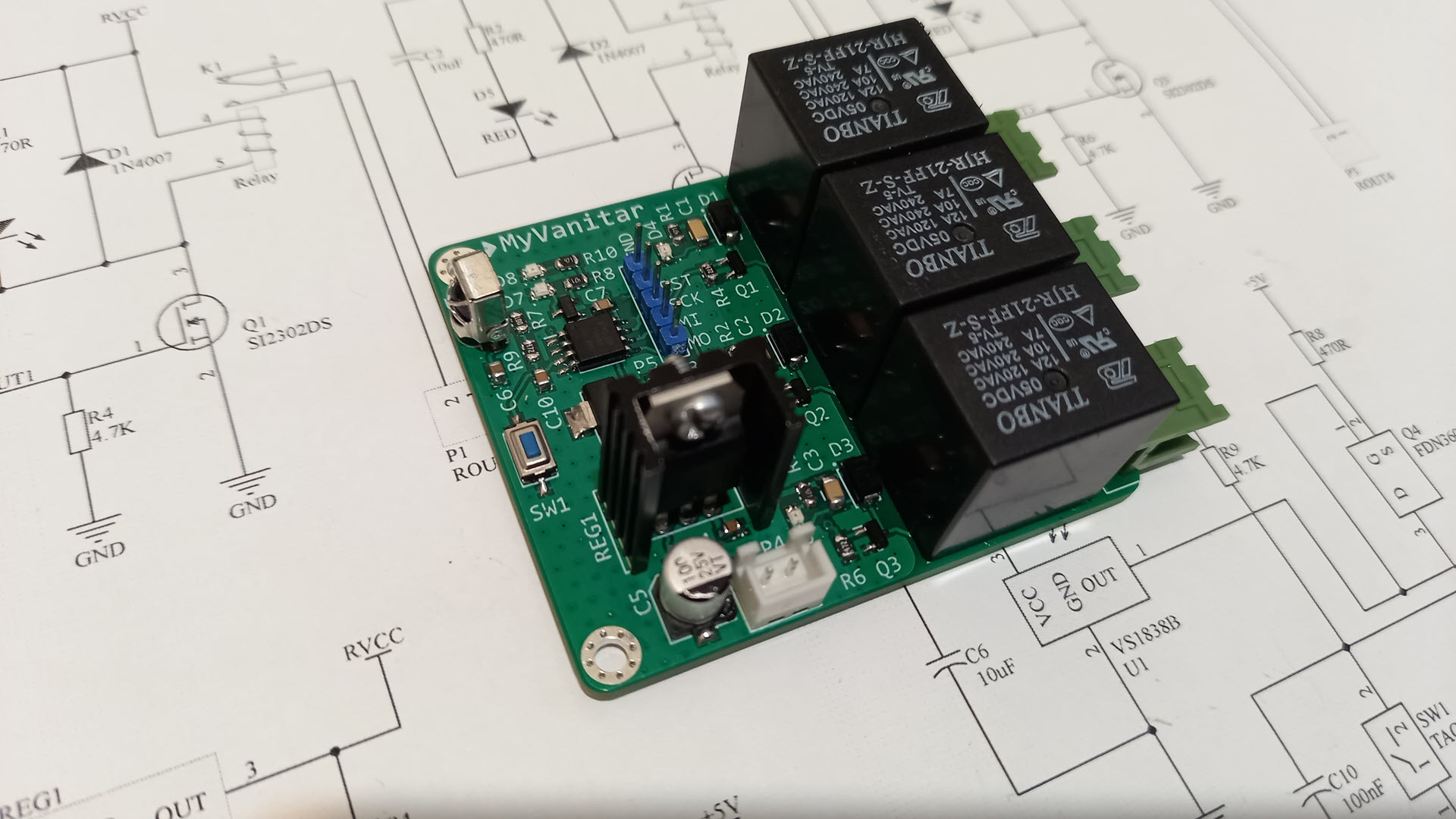
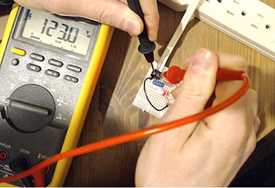
Step 2: The Circuit

Example: Light Bulb Blinking
Connect the power supply 12V (-) to the Light Bulb negative side (-)
Connect power supply 12V (+) to the relay shield - Relay1 pin (COM1)
Connect relay shield - Relay1 pin (NO1) to Light Bulb negative side (+)
Example: Button activates the relay
Connect Arduino Digital pin [2] to the button on the breadboard and Resistor1
Connect the other side of resistor 1 to the breadboard pin [GND]
Connect the Other pin of the button to the breadboard positive pin [5V]
Connect Arduino pin [5V] to breadboard positive pin [Red line]
Connect Arduino pin [GND] to breadboard negative pin [Black line]
Example: Remote Control activates the relay
Connect Remote pin [VCC] to Arduino relay shield pin [5V]
Connect the Remote pin [GND] to the Arduino relay shield pin [GND]
Connect Remote pin [D0] to Arduino relay shield digital pin [2]
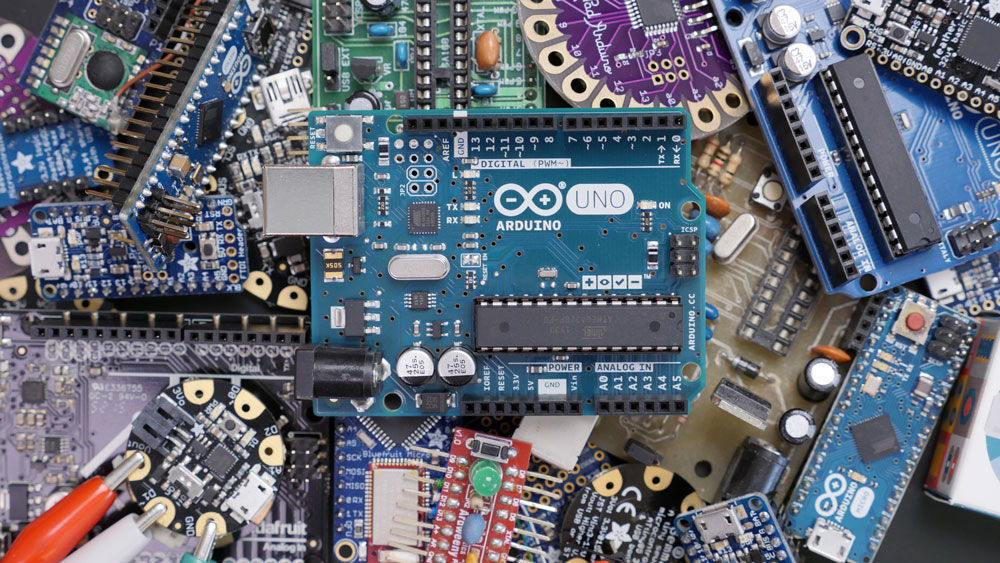
Step 3: Start Visuino, and Select the Arduino Board Type


Start Visuino as shown in the first picture. Click on the "Tools" button on the Arduino component (Picture 1) in Visuino. When the dialog appears, select "Arduino UNO" as shown in Picture 2
Step 4: In Visuino, Add the Shield


In Visuino, click on the board top right button and select "Add Shields".
In the "Shields" window, expand "Relay" and select "Arduino 4 Relays Shield"
Close the "Shields" window
Step 5: In Visuino, Add, Set & Connect Components
For the first Light bulb blinking example, we will add a "Pulse generator" component and connect its pin [Out] to Arduino > Relay1 pin [In]
Upload the project to the Arduino board
For the second Light bulb button or remote control example, we will add "Toggle(T) Flip-Flop" component and "DeBounce button" component
Connect Arduino digital pin [2] to "Button1" pin [In
Connect "Button1" pin [Out] to "Toggle(T) Flip-Flop" pin [Clock]
Connect "Toggle(T) Flip-Flop" pin [Out] to Arduino > Relay1 pin [In]
Upload the project to the Arduino board
Step 6: Generate, Compile, and Upload the Arduino Code

In Visuino, at the bottom, click on the "Build" Tab, make sure the correct port is selected, then click on the "Compile/Build and Upload" button.
Step 7: Play
Congratulations! You have completed your project with Visuino. Also attached is the Visuino project that I created for this project. You can download it and open it in Visuino: https://www.visuino.com
Download Visuino file: Relay-Shield.visuino
Download Visuino file: Relay-Shield-Button-Or-Remote.visuino