ESP32 C3 OLED - Get Time and Date From Internet
2025-06-03 | By Ron Cutts
License: General Public License Displays Real Time Clocks (RTCs) Wifi Arduino ESP32
Step 1: What You Will Need


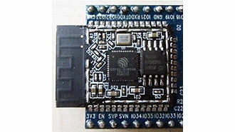
ESP32 C3 OLED
Visuino program: Download Visuino
Step 2: Start Visuino, and Select the DIY More ESP32 C3 0.42" OLED Board Type


Start Visuino as shown in the first picture Click on the "Tools" button on the Arduino component (Picture 1) in Visuino When the dialog appears, select "DIY More ESP32 C3 0.42" OLED" as shown on Picture 2
Note: there are a few different ESP32 C3 OLED boards to choose, make sure that you select the one that fits your board
Step 3: WiFi Setup


Select DIY More ESP32 C3 0.42" OLED board and in the editor Modules>WiFi>Access Points, click on [...] button, so that the "Access points " window will open. In this editor drag the WiFi access point to the left side.
In the properties window under "SSID" put the name of your WiFi Network
Under "Password" put the access password for your WiFi network
Close the "Access points" window
On the left in the editor select Modules>Wifi>Sockets, click on [...] button, so that the "Sockets" window will open. Drag the TCP/IP Client from right to the left side, then under the Properties window, set port: 37 and host: time-c-g.nist.gov
Close the "Sockets" window
Step 4: In Visuino Add Components


Add "Pulse Generator" component
Add "Internet Time Protocol" component
Add 2X "Delete Right Sub Text" component
Add 2X "Delete Left Sub Text" component
Add "Date/Time Multi Source" component
Step 5: In Visuino Set Components


Select "PulseGenerator1" and in the properties window set frequency to 0.1166667
Select "DeleteRightText1" and in the properties window set Length to 13
Select "DeleteRightText2" and in the properties window set Length to 5
Select "DeleteLeftText2" and in the properties window set Length to 12
Select DIY More ESP32 C3 0.42" OLED and in the editor Modules>Display>Elements, click on [...] button, so that the "Elements" window will open.
In the Elements dialog drag 2X "Text Field" from the right side to the left
Select "Text Field2" and in the properties window set "Y" to 20
Close the Elements Dialog
Step 6: In Visuino Connect Components
Connect "PulseGenerator1" pin [Out] to "InternetTime1" pin [In]
Connect "InternetTime1" pin [Socket] to "DIY More ESP32 C3 0.42" OLED" >TCP Client1 pin [In]
Connect "InternetTime1" pin [Out] to "MultiSource1" pin [In]
Connect "MultiSource1" pin [0] "DeleteRightText1" pin [In] and "DeleteRightText2" pin [In]
Connect "DeleteRightText1" pin [Out] to "DeleteLeftText1" pin [In]
Connect "DeleteRightText2" pin [Out] to "DeleteLeftText2" pin [In]
Connect "DeleteLeftText1" pin [Out] to DIY More ESP32 C3 0.42" OLED" >"Display ">Text Field1 pin[In]
Connect "DeleteLeftText2" pin [Out] to DIY More ESP32 C3 0.42" OLED" >"Display ">Text Field2 pin[In]
Step 7: Generate, Compile, and Upload the Code

In Visuino, at the bottom, click on the "Build" Tab, make sure the correct port is selected, then click the "Compile/Build and Upload" button.
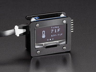
Step 8: Play
If you power the board, it will connect to the internet, and the display should start showing the date and time from the NIST server. You can also experiment with other servers that you can find here https://tf.nist.gov/tf-cgi/servers.cgi
Congratulations! You have completed your Internet Time project with Visuino. Also attached is the Visuino project, that I created for this Tutorial. You can download and open it in Visuino: https://www.visuino.eu
Download Visuino file: esp32-C3-oled-Internet-Time.visuino