DIY Super Nintendo Breadboard Controller
2016-09-15 | By Benjamin Santiago
License: None
For people who spent their childhood at home in front of a TV playing video games, nothing holds more nostalgic power than a Super Nintendo. Fast forward to present day and you can relive your younger glory days with the use of a few spare parts and a little imagination.
For this project we will attempt to replicate a Super Nintendo controller. As with every other project, draw your schematic diagram and make sure you have every component. In this case, you will need the following components:
breadboard
connecting wires
sixteen 10K Ohm resistors
12 push buttons
two 4021 PISO shift registers and
Super Nintendo control cable
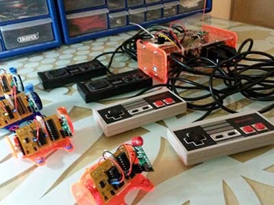
Before soldering anything, it is always best to begin with a prototype and make sure everything is in order. For this step, a breadboard will be your best friend. We also need 12 buttons because that is the amount of contact points there are for the controller. The two shift registers are used to connect the 12 buttons and the 16 resistors.
The 4021 is parallel to serial shift register, and it’s main responsibility is to take the parallel input and convert it to a serial pulse of data from whichever button is being pushed. The best way to think about the operation is to liken it to a conveyor belt. The NES is constantly outputting a clock signal and every time it wants to know what buttons are being pressed, it briefly activates the Parallel-Serial line (think of it as a "load" line) causing the 4021 to “load” each button as one bit. Every time the clock pulses the “conveyor belt” moves one bit along the line.
We have two 4021s due to the number of buttons, and both are connected to form a longer conveyor belt. The first 4021’s output is fed onto the second 4021 via a serial input which has been colored green on the schematic below. The Nintendo activates the “load” line every sixteen bits and then waits while the clock line shifts the conveyor 16-bits along. Once all sixteen bits are received, the load line is activated again and the bits are reloaded onto the belt.
Here, the schematic is colored for easy viewing. As mentioned above, the green connection is where data moves across the two shift registers. The red connection is the “load” line and each blue line indicates the inputs or buttons for the control.
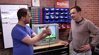
Each line is held “high” by the 5V power and the 10K resistor until a switch is pressed, grounding the pin. To make a NES connector, simply ignore the second IC. You can then connect your circuit to a Super Nintendo cable that hooks up to a device play games using your old console. And don’t forget to have loads of fun!
Source: https://www.youtube.com/watch?v=Ot-WMdTQEII