DIY Solder Stencil Vacuum Table with Shop Vacuum
2025-08-26 | By Zach Hipps
License: See Original Project 3D Printing
When it comes to assembling and soldering PCBs, there are a lot of different approaches you can take. Sometimes, I hand-place and hand-solder each individual component, but if I have a lot of boards to do, it's definitely faster to order a solder stencil. However, solder stencils can be tricky to get right. In my experience, if I don't have them perfectly flat, I'll often deposit too much solder paste, which causes problems down the road.
Hello, my name is Zach, and I'm the Byte Sized Engineer. In this post, I want to see if I can solve this problem using my shop vac.
To start off, I wanted to explain the technique that I have been using for years. It’s the tried-and-true method I’ve seen everybody else use. The idea is that you use spare boards to create a perimeter around the board you want to apply the solder paste to.
I was curious, though, how long this took. So, I took out my phone and used the stopwatch app to time myself. I placed out all the perimeter boards and then taped them down. Now, I could slide each PCB in and out, but here came the hard part: I needed to align the holes in my stencil with all of the footprints. Once I had it aligned, I carefully tore off some tape and placed it down, making sure not to cover any of the holes, so I positioned it along the top edge. That whole process took me two minutes and eight seconds. It didn't take an enormous amount of time, but the process was a little finicky. Unfortunately, the stencil had a bit of an air gap underneath it, and that has always bothered me. Stencils work best when they are perfectly flat against the PCB. There had to be a better way to do this, and I had an idea.
I removed the solder stencil and brought the PCB over to my workbench. I was thinking about CNC router tables, and I'd seen people use a vacuum or draft table to hold down their workpiece, and it is surprisingly strong! If I could use my shop vac to hold the stencil down to the PCB, I could achieve a nice, flat interface, which would lead to much better results with the solder paste. I grabbed my shop vac to see if this idea was going to work. It might be a failure from the start. Fortunately, that first test worked well. The edges weren't getting any suction, so they were peeling up, but if I could figure out some way to apply even suction across the whole surface area, I think this might work.
Let me explain what I was thinking. I was thinking that I needed to create a box. In the center of the box, I'd have the PCB. Then, I needed the stencil to sit on top of the PCB. I also needed to include some features that would help me align the PCB and the stencil, so I didn't have to do that by eye. The last thing I needed to do was attach the vacuum hose, so I'd need a feature for that. I wanted to be able to use this for other circuit boards, so I thought this needed to be in multiple pieces. I'd have the main base, and then an insert that could be customized for different-sized PCBs.
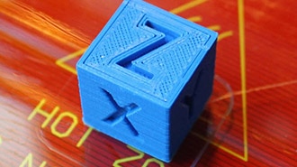
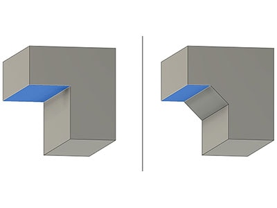
With all of this in mind, I was ready to start 3D modeling this on my computer. The nice thing was that I didn't have to take physical measurements because the circuit board and the stencil were both designed digitally on the computer, so I could just bring those models right into my modeling software. First, I needed a sort of insert that would hold the PCB. So, I created a sketch, extruded that out, and created a little shelf. The PCB was actually going to fit inside it, and I wanted to make sure that I gave myself enough clearance so that I could easily slide it in without it moving around too much. Next, I needed to add a second, thinner shelf, where the solder stencil would fit. It was aligned with the PCB, so I didn't have to align the stencil with the PCB visually. My jig should do that for me, so that would save me some time. Then I just added some fillets because both the PCB and the stencil had rounded corners. That took care of the insert. The next thing I needed to do was create the actual vacuum table. I extruded a large box, and then I had a hollow space where the vacuum pressure could be applied to the PCB. The next thing I needed to do was to create a way for me to remove the stencil and the PCB. I created these little divots that allowed you to get the tip of your finger in there and pull out the PCB and stencil. The final thing I needed to do was create the adapter for the vacuum hose, which I thought was the hardest part of the 3D modeling process. I had to create a sketch plane that was offset at an angle, but once I had that all set up, I was able to make a loft between the hose adapter and our box, and it looked really good. I was happy with how this turned out, and then I was ready to 3D print it to see if it worked.
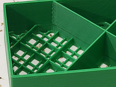
After pulling it off the printer, I wanted to check and see what worked and what didn't. The first thing I needed to check was how well the circuit board fit in the shelf. It looked like I actually didn't give it enough clearance, so I needed to add a little bit of dimension there so that the circuit board fits in there. Next, I tried the stencil and saw how it fit. It did go in, but it had a bit of slop, so I should tighten up that dimension. The bigger question was the base. The insert sits in the top, and I noticed I left too much slop in that dimension. I should tighten it up, so the insert is cleaner and slides in more smoothly. But most importantly, did the shop vac hose fit? Yeah, it did go on there, but again, I probably had a little bit too much slop in there, so I could tighten that up.
I made those changes and then reprinted version two. One cool thing about this design is that if I wanted to use this with a different PCB, I didn't have to actually reprint the whole thing. All I needed to do was design a custom insert for the next PCB and just print that out, and that would go in the universal main body. Let's see if all my changes worked. Oh yeah, this version was a much better fit, and the little holes for my fingertips worked really well. The PCB also fits in there so much better. I nailed that dimension. It's always nice when you get that right. And now the stencil... the stencil did have a little bit of wiggle room, but that allowed me to fine-tune the alignment with the footprints below, so I wasn't too worried about that. This was really good. I was optimistic about this. I thought it was going to work, but I wouldn't know until I connected it up to the shop vac.
Just like before, I was curious to see how long this process took, so I started my stopwatch. The first thing I needed to do was to insert the PCB. I got the clearance just perfect. I inserted the stencil, and it mostly aligned itself. I could fine-tune that right before I turned on the vacuum. I put the insert in the vacuum base. This was ready to put solder paste on! That was so much faster than the previous method. It only took about 35 seconds. Granted, I did have to model and 3D print all these parts, but that was a one-time investment. Now, I had this ready for the next time I needed to solder these boards. It was time to put on some solder paste, and before I turned the vacuum on, I just wanted to make sure the alignment was perfect. As I was using the squeegee to move the paste around, everything stayed in place. I removed the stencil. That worked so well.
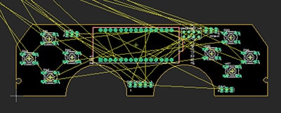
I did want to point out the footprint on the board for U2. It is an integrated circuit that has really fine pitch leads on it. Before, when I would do something like this, it would deposit too much solder paste, and then when I reflowed it, I would get solder bridges, and that would cause problems. Now, using this method, it seemed like it had the exact right amount of solder paste, and I wouldn't be as worried about solder bridges when I went to reflow this board.
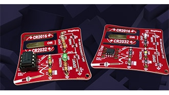
To wrap this up, I wanted to compare the previous tried-and-true method with my new solder stencil vacuum table. Did this work better? And the answer was, yes, I thought it did. It was certainly faster to do, minus all of the time that it took me to model and print it out. I think I’m going to be using this moving forward. I liked that I didn't have to worry about depositing too much solder paste and having solder bridges. This circuit board was for a DIY custom macro pad that I built in a previous video. If you haven't seen that video yet, I highly recommend it!
You can find the 3D model files, print settings, and additional information for this project here: https://github.com/bytesizedengineering/solderStencilVacuumTable