Mfr Part # A000067
ARDUINO MEGA2560 ATMEGA2560
Arduino
License: Attribution Oscilloscope Serial / UART Arduino
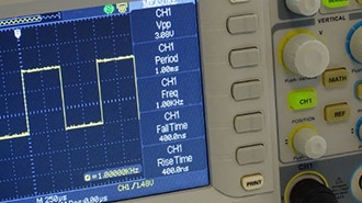
Oscilloscopes are fun engineering equipment that allow us to see how the voltage of a signal varies with time, and measure useful values such as frequency, peak-to-peak voltage, DC offset, and more. However, many oscilloscopes are bulky and may be expensive. In this project, we will explore building a portable, low-cost oscilloscope using:
Some standard functions in an oscilloscope that I will implement are:
Peak-to-peak
Vmax
Vmin
DC offset (Vavg)
Frequency
Calibrate
Lastly, since I do not want to use a signal generator, I will use a potentiometer to generate a wave manually.
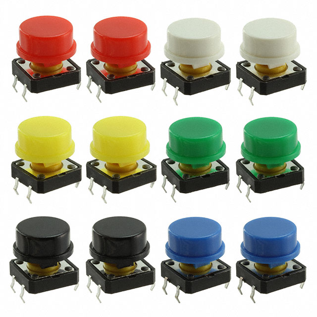
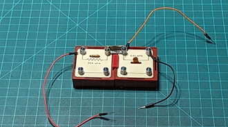
Here’s an image of my put-together circuit, and a table mapping buttons to functions:
Side note: Pull-up resistors
Note how there is no resistor between the push buttons and the digital pins or ground. This is contradictory to Arduino’s tutorial on “How to Wire and Program a Button,” where they use a pull-down resistor. This is because I am instead using a pull-up resistor that is built into the Arduino, and I do this by declaring the pin as an INPUT_PULLUP in the code, as you will see.
Let’s see how a pull-up resistor works.
Code
Here is my full code if you want to give it a read before we dive into the functions individually:
#include <Arduino.h>
#include <LiquidCrystal.h>

void calibrate();
void findMaxVoltage();
void findMinVoltage();
void findAvgVoltage();
void peakToPeak();
float mapVoltage();
void findFrequency();

//declare 6 button pins
const int pk2pkButton = 6;
const int vmaxButton = 7;
const int vminButton = 8;
const int vavgButton = 9;
const int frqButton = 10;
const int calibrateButton = 13;

float minVoltage = 10.0; // Initialize min voltage to a high value
float maxVoltage = -10.0; // Initialize max voltage to a low value
float avgVoltage = 0.0; // Initialize average voltage to 0.0
float peakToPeakVoltage = 0.0; // Initialize peak-to-peak voltage to 0.0

//declare ADC pin to act as oscilloscope probe
const int probe1 = A0; // ADC pin for probe 1

float frequency = 0.0; // Frequency variable

// initialize the library by associating any needed LCD interface pin
// with the arduino pin number it is connected to
const int rs = 12, en = 11, d4 = 5, d5 = 4, d6 = 3, d7 = 2;
LiquidCrystal lcd(rs, en, d4, d5, d6, d7);

void setup() {

  // set up the LCD's number of columns and rows:
  lcd.begin(16, 2);
  // Print a message to the LCD.
  lcd.print("hello, world!");
  delay(2000); // Wait for 2 seconds
  lcd.clear(); // Clear the LCD

  // Set button pins as input with pull-up resistors
  pinMode(pk2pkButton, INPUT_PULLUP);
  pinMode(vmaxButton, INPUT_PULLUP);
  pinMode(vminButton, INPUT_PULLUP);
  pinMode(vavgButton, INPUT_PULLUP);
  pinMode(frqButton, INPUT_PULLUP);
  pinMode(calibrateButton, INPUT_PULLUP);
  pinMode(probe1, INPUT); // Set probe pin as input

  lcd.print("calibrating on start up...");
  delay(2000); // Wait for 2 seconds
  Serial.begin(9600);
  calibrate(); // Call the calibration function
  lcd.clear();
  lcd.print("ready!");
}

void loop() {
  float voltage = analogRead(probe1); // Read the voltage from probe 1
  voltage = mapVoltage(voltage);
  Serial.println(voltage);

  if (digitalRead(pk2pkButton) == LOW) {
    lcd.clear();
    lcd.print("pk2pkButton pressed");
    lcd.setCursor(0, 1); // Set cursor to second line
    peakToPeak(); // Call the function to find peak-to-peak voltage
    lcd.print("pk2pk: ");
    lcd.print(peakToPeakVoltage);
    lcd.print(" V");
  }

  if (digitalRead(vmaxButton) == LOW) {
    lcd.clear();
    lcd.print("vmaxButton pressed");
    lcd.setCursor(0, 1); // Set cursor to second line
    findMaxVoltage(); // Call the function to find max voltage
    lcd.print("Max: ");
    lcd.print(maxVoltage); // Print max voltage
    lcd.print(" V");
  }

  if (digitalRead(vminButton) == LOW) {
    lcd.clear();
    lcd.print("vminButton pressed");
    lcd.setCursor(0, 1); // Set cursor to second line
    findMinVoltage(); // Call the function to find min voltage
    lcd.print("Min: ");
    lcd.print(minVoltage); // Print min voltage
    lcd.print(" V");
  }

  if (digitalRead(vavgButton) == LOW) {
    lcd.clear();
    lcd.print("vavgButton pressed");
    lcd.setCursor(0, 1); // Set cursor to second line
    findAvgVoltage(); // Call the function to find average voltage
    lcd.print("Avg: ");
    lcd.print(avgVoltage); // Print average voltage
    lcd.print(" V");
  }

  if (digitalRead(frqButton) == LOW) {
    lcd.clear();
    lcd.print("frqButton pressed");
    lcd.setCursor(0, 1); // Set cursor to second line
    findFrequency(); // Call the function to find frequency
    lcd.print("Freq: ");
    lcd.print(frequency); // Print frequency
    lcd.print(" Hz");
  }

  if (digitalRead(calibrateButton) == LOW) {
    lcd.clear();
    lcd.print("calibrateButton pressed");
    delay(1000); // Wait for 1 second
    calibrate(); // Call the calibration function
    delay(50);
  }
}

void calibrate() {

  lcd.clear();
  lcd.print("Calibrating...");
  //measure voltages from probe for 30 seconds to find min and max
  unsigned long startTime = millis();
  float voltage;
  maxVoltage = -10.0;
  minVoltage = 10.0;

  while (millis() - startTime < 10000) { // 30 seconds
    voltage = analogRead(probe1); // Read the voltage from probe 1
    //voltage = map(voltage, 0, 1023, 0, 5000) / 1000; // Convert to volts DOES NOT HANDLE FRACTIONS
    voltage = mapVoltage(voltage);
    if (voltage < minVoltage) {
      minVoltage = voltage; // Update min voltage
    }
    if (voltage > maxVoltage) {
      maxVoltage = voltage; // Update max voltage
    }
    Serial.println(voltage);
  }

  avgVoltage = (maxVoltage + minVoltage) / 2; // Calculate average voltage
  startTime = millis(); // Reset start time for frequency measurement
  unsigned long crossingTime = 0; // Initialize crossing time
  int crossings = 0; // Initialize crossing count
  frequency = 0.0; // Reset frequency
  while (millis() - startTime < 10000) { // 30 seconds
    voltage = digitalRead(probe1);
    voltage = mapVoltage(voltage);
    if (voltage == avgVoltage) {
      crossings++;
      crossingTime += millis() - startTime - crossingTime; // Time since the last crossing
    }
    Serial.println(voltage);
  }
  if (crossings > 0) {
    crossingTime /= crossings; // Average time between crossings
    // Calculate frequency from time period
    long period = crossingTime  4; // Time period in milliseconds
    frequency = 1/(period1000); // Frequency in Hz
    lcd.setCursor(0, 1); // Set cursor to second line
    lcd.print("Freq: ");
    lcd.print(frequency);
    lcd.print(" Hz");
    lcd.setCursor(0, 0); // Set cursor to first line
    delay(100); // Small delay to avoid rapid reading
  }
  delay(3000);
  lcd.clear();
  lcd.print("Calibration done!");
  delay(1000);
}

//find max voltage in 10 seconds
void findMaxVoltage() {
  unsigned long startTime = millis();
  maxVoltage = -10.0; // Reset max voltage
  while (millis() - startTime < 10000) { // 10 seconds
    float voltage = analogRead(probe1); // Read the voltage from probe 1
    voltage = mapVoltage(voltage);
    if (voltage > maxVoltage) {
      maxVoltage = voltage; // Update max voltage
    }
    Serial.println(voltage);
    //delay(100);
  }
}
//find min voltage in 10 seconds
void findMinVoltage() {
  unsigned long startTime = millis();
  minVoltage = 10.0; // Reset min voltage
  while (millis() - startTime < 10000) { // 10 seconds
    float voltage = analogRead(probe1); // Read the voltage from probe 1
    voltage = mapVoltage(voltage);
    if (voltage < minVoltage) {
      minVoltage = voltage; // Update min voltage
    }
    Serial.println(voltage);
    //delay(100);
  }
}
//find average voltage in 10 seconds
void findAvgVoltage() {
  unsigned long startTime = millis();
  float totalVoltage = 0.0; // Initialize total voltage
  int count = 0; // Initialize count of readings
  while (millis() - startTime < 10000) { // 10 seconds
    float voltage = analogRead(probe1);
    voltage = mapVoltage(voltage);
    totalVoltage += voltage; // Add to total voltage
    count++;
    //delay(100);
    Serial.println(voltage);
  }
  avgVoltage = totalVoltage / count;
}

//find peak to peak voltage in 10 seconds
void peakToPeak() {
  unsigned long startTime = millis();
  float minVoltage = 10.0;
  float maxVoltage = -10.0;
  while (millis() - startTime < 10000) { // 10 seconds
    float voltage = analogRead(probe1);
    voltage = mapVoltage(voltage);
    if (voltage < minVoltage) {
      minVoltage = voltage;
    }
    if (voltage > maxVoltage) {
      maxVoltage = voltage;
    }
    Serial.println(voltage);
    //delay(100);
  }
  peakToPeakVoltage = maxVoltage - minVoltage; // Calculate peak-to-peak voltage
}

void findFrequency() {
  unsigned long startTime = millis();
  unsigned long halfPeriod = 0;
  int crossings = 0;
  for (crossings =0; crossings < 10; crossings++) {
    float voltage = analogRead(probe1); // Read the voltage from probe 1
    voltage = mapVoltage(voltage);
    if (voltage == avgVoltage) {
      halfPeriod += millis() - startTime - halfPeriod; // Time since the last crossing
    }
    Serial.println(voltage);
  }
  if (crossings > 0) {
    halfPeriod /= crossings; // Average time between crossings
    // Calculate frequency from time period
    long period = halfPeriod  2; // Time period in milliseconds
    frequency = 1/(period1000); // Frequency in Hz
  }
}

float mapVoltage(float voltage) {
  if (voltage < 511.5)
    return -((511.5 - voltage)  5.0 / 511.5);
  else
    return ((voltage - 511.5)  5.0 / 511.5);
}
Vmax, Vmin, pk2pk
I read the analog pin measurement connected to the potentiometer for 10 seconds and find the maximum and minimum voltages the waveform takes within those 10 seconds. The difference between the two is the peak-to-peak value.
//find peak to peak voltage in 10 seconds
void peakToPeak() {
  unsigned long startTime = millis();
  float minVoltage = 10.0;
  float maxVoltage = -10.0;
  while (millis() - startTime < 10000) { // 10 seconds
    float voltage = analogRead(probe1);
    voltage = mapVoltage(voltage);
    if (voltage < minVoltage) {
      minVoltage = voltage;
    }
    if (voltage > maxVoltage) {
      maxVoltage = voltage;
    }
    Serial.println(voltage);
    //delay(100);
  }
  peakToPeakVoltage = maxVoltage - minVoltage; // Calculate peak-to-peak voltage
}
The custom mapVoltage() vs Arduino map() function
Arduino has a built-in function called map() that can be used to, well, map the 1024 different values the analog pin can read to a value between -5 and 5.
y = map(x, 1, 50, 50, -100);
However, the problem here is that the map() function returns integer values only, so we need to write our own mapping function.
Frequency
I have a very rudimentary method of finding the frequency. My approach is to average the times at which the wave passes the average voltage value to find half the frequency. F = 1/T, so I multiply the average half a period by 2, then take the inverse.
Calibrate
In the first 10 seconds after starting up, I find the frequency and I find the DC offset of the wave by averaging the voltage readings. This section can be modified however we want. Be creative! For example, we cannot input any signal, and any reading picked up can be set as noise and subtracted from our actual readings.
I hope this gave you all a good overview of how to start building a basic digital oscilloscope. I did this in 4 hours for a competition, so I focused on basic functionality more than advanced, high-quality features. Feel free to clone my GitHub repository and add on to the project. Potential additions include building a better interface using Python or using an ESP32 to display the oscilloscope waveform on a webpage!