Mfr Part # 3501
ADAFRUIT GEMMA M0 - MINIATURE WE
Adafruit Industries LLC
License: See Original Project Wearables Gemma
Courtesy of Adafruit
Guide by Irete Hamdani
Overview
Here's a Halloween costume that includes a whole lot of LEDs and a color sensor that determines the colors of those LEDs. The costume is made up of detachable elements that can be added to any dress, skirt, or other piece of clothing.
Parts List
1 x Conductive Thread
1 x USB cable - A/MiniB
1 x Alligator Clips
5 x (Conductive) Metal Snaps
6 x (Conductive) Magnetic Snap
And for the garments:
1 x Black Dress
1 x Petticoat
1 x Black Sash Belt
Initial Setup
For setting up the wiring and initial code, the image above shows an Adafruit NeoPixel Ring instead of the LED strips. In the code, it's just a matter of setting the number of LEDs.
The Adafruit NeoPixel LED Dots Strands come with black plastic connectors. You can take the end connector, clip it off of the last strand and use it to connect the first strand to the microcontroller. This guide gives a good explanation on how to do this properly.
You'll also have 2 additional wires coming out of the female connectors, you can clip them for all of the strands, they won't be needed in this project.
Wiring
Start with alligator clips, sewing will come later.
From the NeoPixels to the Gemma, using the pins on the right side of the Gemma, you connect:
Top strand to GND
Middle strand to D1
Red (bottom) strand to the Vout
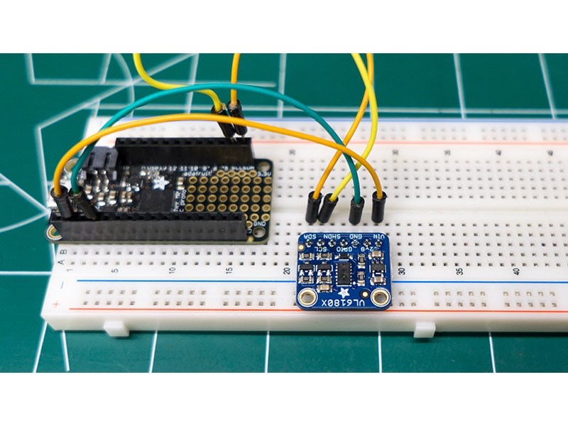
From the Gemma to the Color Sensor, using mostly the pins on the left side of the Gemma, you connect:
SCL (A1/D2) to SCL
SDA (A2/D0) to SDA
3Vo to 3V
GND (on the right side) to GND
In the end, you've should have 2 connections to GND on the Gemma - one from the LED strand(s) and one from the color sensor. And one connection per each of the other Gemma pins.
You also connect the USB connector for uploading the code and later the battery instead of the USB.
Coding
Download the Arduino IDE and the required libraries:
The attached code can work as is. There are a few lines you may consider changing:
1. This project used 9 strands of 20 LEDs, total of 180 LEDs. If you use a different amount, change the number in this line of code:
#define NUM_LEDS 180 // Change this to reflect the number of LEDs you have
2. While working on the project, the lights might be too bright, if so, reduce the number in this line of code. 255 is the maximum for brightness:
#define BRIGHTNESS 255 // Set Brightness here 255
3. In the setup, the following code makes one of the LEDs blink 3 times to let you know that the color sensor is ready to read a color value. For this project, it made sense to light up LED #17 since it was closest to the microcontroller in the layout. You can choose the first LED instead. The counter starts with 0, so change the below to leds[0]. Also, you can change the color of the blinking light. In this code, it goes from Black to White making it blink White.
for (int i=0; i<3; i++){ //this sequence flashes the first pixel three times none/white as a countdown to the color reading.
leds[16] = CRGB::Black;
FastLED.show();
delay(1000);
leds[16] = CRGB::White;
FastLED.show();
delay(500);
}The rest of the code is pretty much a combination of FastLED sample code and Color Sensor code.
In this project, it is set it up so that on restart the color sensor reads the color and the skirt fills up with a transition gradient of that color until the next reset. Similar to the Adafruit Chameleon Scarf project. You can also set it up so that it fires off the color sensor every x second and changes the lights according to the color it picks up. This can be achieved by moving the code starting from tcs.begin(); from the setup() function to the loop() function and doing some modifications.
Download the code by clicking the "Download Project Bundle" button below or via the link here.
To upload code, you need to quickly double press the reset button on the Gemma. You know it's uploading if the green and red lights on the Gemma are on.
// SPDX-FileCopyrightText: 2021 Irete Hamdani for Adafruit Industries
//
// SPDX-License-Identifier: MIT
//
#include <FastLED.h>
#include <Wire.h>
#include "Adafruit_TCS34725.h"

#define DATA_PIN   1
#define LED_TYPE    WS2812B
#define COLOR_ORDER GRB
#define NUM_LEDS    180     // Change this to reflect the number of LEDs you have
#define BRIGHTNESS  255     // Set Brightness here 255

CRGB leds[NUM_LEDS];

// color sensor
// our RGB -> eye-recognized gamma color
byte gammatable[256];
//used to store color sensor received color
uint16_t clear, red, green, blue;

// color sensor
Adafruit_TCS34725 tcs = Adafruit_TCS34725(TCS34725_INTEGRATIONTIME_50MS, TCS34725_GAIN_4X);

void setup() {
  delay(3000); // 3 second delay for recovery

  // tell FastLED about the LED strip configuration
  FastLED.addLeds<LED_TYPE,DATA_PIN, COLOR_ORDER>(leds, NUM_LEDS)
    .setCorrection(TypicalLEDStrip) // cpt-city palettes have different color balance
    .setDither(BRIGHTNESS < 255);

  // set master brightness control
  FastLED.setBrightness(BRIGHTNESS);

  tcs.begin();

  // helps convert RGB colors to what humans see
  for (int i=0; i<256; i++) {
    float x = i;
    x /= 255;
    x = pow(x, 2.5);
    x *= 255;

    gammatable[i] = x;
  }

  for (int i=0; i<3; i++){ //this sequence flashes the first pixel three times none/white as a countdown to the color reading.
    leds[16] = CRGB::Black;
    FastLED.show();
    delay(1000);
    leds[16] = CRGB::White;
    FastLED.show();
    delay(500);
  }

  // turn on LED
  tcs.setInterrupt(false);
  delay(60);  // takes 50ms to read

  tcs.getRawData(&red, &green, &blue, &clear);

  tcs.setInterrupt(true);  // turn off LED
}

void loop()
{
  // Figure out some basic hex code for visualization
  uint32_t sum = red;
  sum += green;
  sum += blue;
  //sum += clear; // clear contains RGB already so no need to re-add it

  float r, g, b;
  r = red; r /= sum;
  g = green; g /= sum;
  b = blue; b /= sum;
  r *= 256; g *= 256; b *= 256;

  CRGBPalette16 gTargetPalette (
   CRGB (gammatable[(int)r], gammatable[(int)g], gammatable[(int)b]));

  colorwaves( leds, NUM_LEDS, gTargetPalette);//gCurrentPalette);

  FastLED.show();
  FastLED.delay(20);
}

// This function draws color waves with an ever-changing,
// widely-varying set of parameters, using a color palette.
void colorwaves( CRGB* ledarray, uint16_t numleds, CRGBPalette16& palette)
{
  static uint16_t sPseudotime = 0;
  static uint16_t sLastMillis = 0;
  static uint16_t sHue16 = 0;

  uint8_t sat8 = beatsin88( 87, 220, 250);
  uint8_t brightdepth = beatsin88( 341, 96, 224);
  uint16_t brightnessthetainc16 = beatsin88( 203, (25 * 256), (40 * 256));
  uint8_t msmultiplier = beat8(147); //beatsin88(147, 23, 60); - creates a more dynamic pattern [IH]

  uint16_t hue16 = sHue16;//gHue * 256;
  uint16_t hueinc16 = beatsin88(113, 300, 1500);

  uint16_t ms = millis();
  uint16_t deltams = ms - sLastMillis ;
  sLastMillis  = ms;
  sPseudotime += deltams * msmultiplier;
  sHue16 += deltams * beatsin88( 400, 5,9);
  uint16_t brightnesstheta16 = sPseudotime;

  for( uint16_t i = 0 ; i < numleds; i++) {
    hue16 += hueinc16;
    uint8_t hue8 = hue16 / 256;
    uint16_t h16_128 = hue16 >> 7;
    if( h16_128 & 0x100) {
      hue8 = 255 - (h16_128 >> 1);
    } else {
      hue8 = h16_128 >> 1;
    }

    brightnesstheta16  += brightnessthetainc16;
    uint16_t b16 = sin16( brightnesstheta16  ) + 32768;

    uint16_t bri16 = (uint32_t)((uint32_t)b16 * (uint32_t)b16) / 65536;
    uint8_t bri8 = (uint32_t)(((uint32_t)bri16) * brightdepth) / 65536;
    bri8 += (255 - brightdepth);

    uint8_t index = hue8;
    //index = triwave8( index);
    index = scale8( index, 240);

    CRGB newcolor = ColorFromPalette( palette, index, bri8);

    uint16_t pixelnumber = i;
    pixelnumber = (numleds-1) - pixelnumber;

    nblend( ledarray[pixelnumber], newcolor, 128);
  }
}Testing with a red object
Testing with a blue object
Assembly
Planning
The petticoat with the microcontroller, battery, and all of the LEDs sits underneath the dress and can't be accessed without pulling up the dress or putting the microcontroller at the bottom making it hard to reach. In addition, the color sensor needs to be in a central place on top of the dress.
The solution to connecting it all together - snaps! Or to be precise conductive snaps.
The idea is to snap the petticoat to the dress, then snap on another element on top of the dress (the belt) to hold the color sensor and then run conductive thread from one set of snaps to the other. This will also enable detaching the belt and the petticoat and connecting them to another dress/skirt.
Finally, there is an on/off reset snap on the dress that runs all the way down to the battery.
Sewing the Petticoat
Planning
Decide on the placement of the microcontroller. That will determine the battery, the snaps that hook up to the dress and the starting point of the LEDs. On the waistline to the left is the recommended placing in order to be as close as possible to where the belt will be on the dress.
Decide on the pattern of the LED strands. They can spiral around the petticoat, swirl around semi randomly, zig zag up and down, whatever. It's recommended to connect them with a whole bunch of safety pins first before sewing them in place. In this project, the LEDs spiral around and around the petticoat. The dress was shorter than the petticoat, so the LEDs spiral finished up before they crossed over the edge of the dress.
Decide on the placement of the snaps. For the petticoat to dress snaps, use the larger magnetic buttons. You can go with either 4 snaps for just the color sensor or 6 snaps for both the color sensor and the on/off switch. You need to space them to make sure you can create separate connections that don't cross each other. And plan the order right so that you have direct lines to the place where the belt will be connected.
Sewing
It is extremely recommended to test all of the time! There's nothing more annoying that having a project not work and try to trace all of the connections to see where there might be a problem.
Fun fact: Alligator clip to the magnetic buttons so they easily connect for testing.
Sew in the microcontroller with some regular black thread to keep it in place. Then start with the LEDs strand's connector. Using conductive thread connect the GND, D1, and Vout on the right to the wiring the connects to the strands.
Sewing the microcontroller
Next sew the snaps to the GND on the right and the SCL (A1/D2), SDA (A2/D0) and 3Vo on the left. Use both the front side and inner side of the petticoat to avoid crossing circuits. You can later sew ribbon on top of each connection to further ensure they won't touch each other and also to avoid irritating the skin on the inner side. There are different techniques for sewing with conductive thread. You can read more about that here.
Sewing the magnetic snaps
Sew up the LED strands. In this project, I sewed around every 5 LEDs either the LED itself or the wiring. Try to follow the natural curves of the petticoat so that the LEDs with flow nicely under the dress. What's nice about the Adafruit LEDs strands is that they barely weight anything and don't burden the petticoat.
Testing with alligator clips connected to the color sensor
For the battery, to have control over resetting the color, plan for a switch closer to the belt on the outside of the dress. To do this, cut the red wire to the battery and split it between 2 snaps. When the switch is "on" it essentially connects these 2 snaps and closes the circuit.
Sewing the battery snaps - notice the red wire is split between them and the black wire is connected directly to the battery.
Also see the sewed on battery pocket.
Lastly add a battery pocket that is held secure with a nonconductive snap to keep it from moving around. There's a nice rubber band trick to keep the wires from detaching from the battery. It’s in nearly all of the Adafruit tutorials, for example here. Make sure you choose the right battery size before sewing the pocket.
Final petticoat part
Sewing the Belt
Planning
Decide on the placement of the belt relative to the dress and where you'll position the belt snaps. In this project, I'm using the smaller snaps for the belt. Lastly, trace the lines between the belt connections and the petticoat connections to ensure separation of the lines.
Remove some of the jewels on the belt to make room for the color sensor.
Sewing
Sew in the color sensor with some regular black thread to keep it in place. Sew conductive thread from the 4 pins on the color sensor to the placement of the belt snaps. The belt is pretty narrow so make sure to space out correctly. A banana type shape for the snaps will probably work best.
Use a scrap piece of black satin and sew it on both sides of the belt sash to both cover the stiches and keep them from touching each other.
Belt - Front, color sensor instead of some of the gems
Belt - Back, snaps need to be spaced out and circuits need to be separate
Bow in the belt back
Instead of just tying the belt on, you can create a bow at the back at the right length and use non-conductive snaps to put it together. You can also add a few non-conductive snaps around the dress to keep the belt in place.
Bow closed
Sewing the Dress
Planning
The snaps on the dress should go according to the plan for sewing the petticoat and the belt. For the 4 color sensor connections, you should align the positioning of the petticoat snaps to their position on the inside of the dress, create direct lines from them to the back side of the belt connections and verify the lines don't intersect.
Plan where on the dress you want to put the on/off switch and align the connection to the remaining 2 magnetic snaps.
Sewing
You can use ribbon to cover up the thread lines. Therefore, you don't need to sew from one snap to other, rather leave the thread flat with some extra room for flexibility. For each connection, start with the petticoat matching snap, sew that on with conductive thread, lay enough thread on the dress and sew the other side of that connection to the back side of where the belt snap will be.
Lay the conductive thread on the inside of the dress from the petticoat snap to the belt snap
Cover the thread with ribbon
Sew on ribbon to conceal the connections and keep them separated.
The snaps on the dress that correspond with the belt snaps
On/Off switch - using another pair of conductive snaps, place a decorative button to connect 2 snaps in a relatively convenient place on the dress.
The on/off switch in 'Off' position
The on/off switch in 'On' position
Final Project and Additional Resources
To put it on, start with putting on the dress, then turn on the microcontroller, hook up the petticoat underneath and then the belt on top, then connect the 'On' switch on the dress.
Additional Resources
Color Sensors - more info on Adafruit color sensors
Color Waves With Palettes - excellent code that goes through predefined color pallets. Can be used instead of using a color sensor
Powering Neo Pixels - depending on how many stands you hook up; you may need a different battery.
FastLED - API documentation