Mfr Part # 169
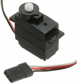
SERVOMOTOR RC 5V TOWERPRO
Adafruit Industries LLC
License: Attribution Arduino
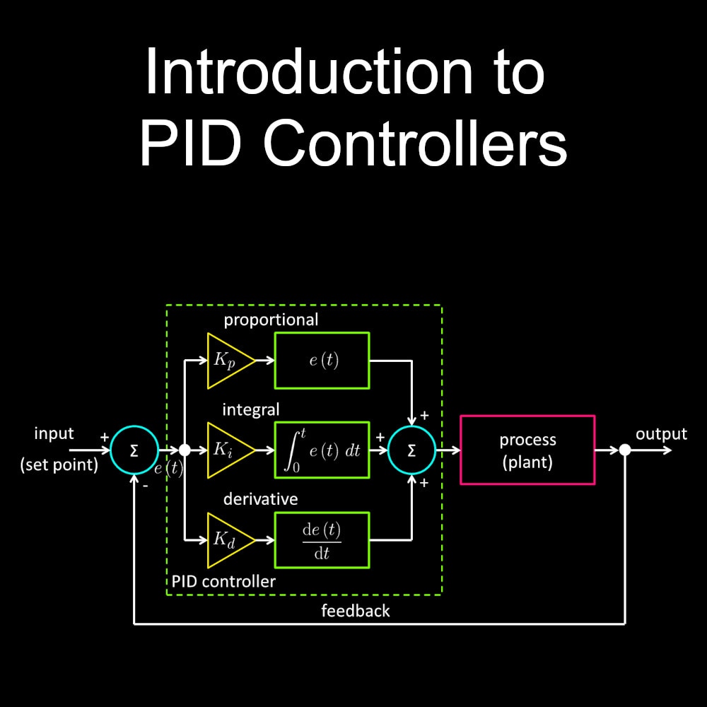
There are many ways to track the sun. A device typically accomplishes this by using a complex analog circuit with photo resistors and a PID controller, but today I will discuss how you can build your own dual-axis solar tracker using only an Arduino and basic solar panel voltage readings.
The required supplies for this project are:
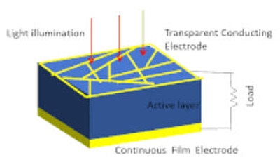
two solar panels
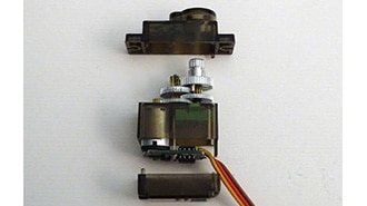
two servos
one stepper motor with controller
three pencils
a small breadboard
cardboard or craft wood
a soldering iron (optional)
and a hot glue gun.
I specifically used two SG92R servos and a 28BYJ-48 stepper motor with a ULN2003 stepper control board, but other common variants should work.
The Build
You first need to create the basic assemblies of this project. You create the first assembly by hot-gluing a servo to the edge of one of the solar panels. The solar panel I used also needed wires soldered onto its terminals, but not all will. Use ample hot glue on cable connections to add strain relief.
If you choose to do a double solar panel tracker, make a left and right-handed version of the solar panel assembly.
It is now time to create the top-base assembly. Make a 6-inch diameter circle, placing the stepper motor through the center. I chose to do this out of craft wood, but cardboard will also work fine.
I used bolts to reinforce the stepper attachment and provide a place to mount the future solar panel assembly, but they are not entirely necessary. Just ensure a stable attachment.
You now need to create a stable bottom-base for the top assembly to rotate on. I did this by creating a cross about 7 inches across, but feel free to experiment with different shapes and sizes. The center of this base needs to be built up to allow the stepper motor shaft to be fixed to it. Two pencils were joined to the bottom-base to allow the top-base to easily slide on the plastic surface and remain balanced.
At this point, both bases will be connected by the stepper motor, and the basic components are mounted to the top base. An empty mechanical pencil is mounted to the bolt but can be glued to the base. This pencil will be a post that allows the solar panel assemblies to be mounted. This assembly step should look like this.
The solar panels will be mounted by inserting the single arm brackets into the mechanical pencil, and all components will be wired according to this schematic:
Your final assembly will look like this. I added the second 9V battery to power the Arduino directly (not shown in the photo) because a single battery did not provide enough power. It is also important to distribute the servos and the stepper motor to two different sides of the power supply, because each side has a single power regulator that individually will not provide enough power for all components.
This is the end of the build phase. After tightening up and verifying proper connections, it is time to program the solar tracker.
The Code
The code for this project is simple and works in two different steps. The first step that only runs once when the Arduino is reset/powered on is an “initial adjustment.” This rotates the whole assembly 360 degrees and finds the direction with the highest solar activity (solar panel voltage). After this function, both solar panels do the same thing: they rotate 180 degrees and find the location with the highest solar activity. There is one standard function for adjusting the base and one for the panels. This allows additional panels to be easily added to this project by calling this one function with the new solar panel and servo.
The second step of this code is an “incremental adjustment” that moves the panels and the base to find a more optimal location for solar activity. It accomplishes this by rotating the base a set number of degrees one direction and probs the solar activity. If the voltage is higher, it retains that new location, if it is lower it rotates in the opposite direction and tests for a higher voltage. If neither test position has a higher voltage, it returns to the original position before attempting to adjust. The solar panels adjust in a similar way. There is one standard function for the panels and one for the base.
The most complicated aspect of programming this project is how Arduino references stepper and servo motors. Using standard libraries, you reference servos with absolute position, but stepper motors with relative position. This creates a confusing dynamic that makes it a challenge to successfully code both modules.
The code is available below. Various delays can be adjusted to make your project more unique. The delays in the main loop can be adjusted to change how often the assembly tries to adjust to attempt to find a more optimal position. You should first load the code using an Arduino USB cable, disconnect the cable, and finally turn on the power supply and connect the Arduino battery.
//2-axis Digital Solar Tracker

#include <Servo.h>
#include <Stepper.h>

//Define constants, servos, flags, and voltage references
const int STEPS_PER_REV = 2048;
int       InitialFlag   = 0;
#define   VOLTAGE_RIGHT A0
#define   VOLTAGE_LEFT  A1
Stepper   Base = Stepper(STEPS_PER_REV, 8, 10, 9, 11);
Servo     Left;
Servo     Right;

//Initially adjusts panel to find strongest light source
int Panel_Initial_Adjustment(Servo &SolarServo, int VoltagePin)
{
	//Constants
	int Voltage     = 0;
	int TestVoltage = 0;
	int Position    = 0;

	delay(500);
	//Loops through position 0-180 degrees to find position of highest voltage
	for (int TestPosition = 0; TestPosition < 180; TestPosition += 5)
	{
		SolarServo.write(TestPosition);
		delay(100);
		TestVoltage = analogRead(VoltagePin);

		//Tests voltage at new position and if greater, saves position
		if (TestVoltage > Voltage)
		{
			Voltage  = TestVoltage;
			Position = TestPosition;
		}
	}
	return Position; //Passes servo position for peak voltage
}

//Incrementally adjusts panel to follow light source
int Panel_Incremental_Adjustment(Servo &SolarServo, int VoltagePin)
{
	//Constants
	int Voltage       = analogRead(VoltagePin);
	int TestVoltage   = 0;
	int TestIncrement = 5; //Degrees servo moves per adjustment
	int Position      = SolarServo.read();
	int TestPosition  = Position;
	int MovementDelay = 500;

	//Probes voltage in a positive and negative angle adjustment. Compares initial angle, positive angle, and negative angle.
    TestPosition += TestIncrement; //Adjusts to probe voltage at positive angle
    SolarServo.write(TestPosition);
    delay(MovementDelay);
    TestVoltage = analogRead(VoltagePin);
    if (TestVoltage > Voltage)
	{
		Voltage  = TestVoltage;
		Position = SolarServo.read();
    }
    else
    {
		TestPosition -= 2*TestIncrement; //Overshoots initial position to probe voltage at negative angle
		SolarServo.write(TestPosition);
		delay(MovementDelay);
		TestVoltage = analogRead(VoltagePin);
		if (TestVoltage > Voltage)
		{
			Voltage  = TestVoltage;
			Position = TestPosition;
		}
    }
  return Position; //Returns servo position for peak voltage
}

//Initially adjusts base to find strongest light source
void Base_Initial_Adjustment(Stepper &BaseStepper, int VoltagePin1, int VoltagePin2, int StepsPerRev)
{
	//Constants
	int CurrentPosition = 0;
	int PeakPosition    = 0;
	int TestVoltage     = 0;
	int Voltage         = 0;
	int DegreesPerTest  = 5;                        //Change to vary how many points base probes
	int Increments      = 360/DegreesPerTest;
	int Step            = (StepsPerRev/Increments); //Amount base rotates between each voltage probe (do not change)

	//Rotates testing voltage incrementally
	for (int TestPosition = 0; TestPosition < Increments; TestPosition += 1)
	{
		CurrentPosition += Step;
		Base.step(Step);
		delay(20);
		TestVoltage = analogRead(VoltagePin1) + analogRead(VoltagePin2);

		if(TestVoltage>Voltage)
		{
			PeakPosition  = CurrentPosition;
			Voltage       = TestVoltage;
		}
	}
	int DistanceToPeak = PeakPosition - CurrentPosition;
	Base.step(DistanceToPeak);
}

//Incrementally adjusts base to follow light source
void Base_Incremental_Adjustment(Stepper &BaseStepper, int VoltagePin1, int VoltagePin2, int StepsPerRev)
{
	//Constants
	int MovementDelay = 500; //Increases delay from base movement to voltage probe
	int TestVoltage   = 0;
	int Voltage       = analogRead(VoltagePin1) + analogRead(VoltagePin2);
	int Step 	  = (StepsPerRev / 36 );


	Base.step(Step); //Moves one test step clockwise of initial position
	delay(MovementDelay);
	TestVoltage = analogRead(VoltagePin1) + analogRead(VoltagePin2);
	if(TestVoltage > Voltage)
	{
		return; //Exits function if higher voltage in test position
	}
	else
	{
		Base.step(-2*Step); //Moves one test step counterclockwise of initial position
		delay(MovementDelay);
		TestVoltage = analogRead(VoltagePin1) + analogRead(VoltagePin2);
		if(TestVoltage > Voltage)
		{
			return;
		}
	}
	Base.step(Step); //Moves back to initial position if neither test step yields higher voltage
}

void setup()
{
	Base.setSpeed(7);
	Left.attach  (2);
	Right.attach (3);
	pinMode(VOLTAGE_LEFT,  INPUT);
	pinMode(VOLTAGE_RIGHT, INPUT);
	pinMode(4,             INPUT);
}

void loop()
{
	//Initial part of main that finds light source
	if (InitialFlag == 0)
	{
		delay(5000); 	    //Initial delay to allow adruino to power on
		Left.write (160); //Initial angle for finding light source
		Right.write(80);
		Base_Initial_Adjustment(Base, VOLTAGE_LEFT, VOLTAGE_RIGHT, STEPS_PER_REV);
		Left.write (Panel_Initial_Adjustment(Left,  A0));
		Right.write(Panel_Initial_Adjustment(Right, A1));
		InitialFlag = 1;  //Flag used to disable after initial adjustment
	}

	//Continual part of main that tracks light source
	{
		delay(500); //Time between incremental adjustments
		Left.write (Panel_Incremental_Adjustment(Left,  A0));
		Right.write(Panel_Incremental_Adjustment(Right, A1));
		Base_Incremental_Adjustment(Base, VOLTAGE_LEFT, VOLTAGE_RIGHT, STEPS_PER_REV);
	}
}
Debugging
A few considerations should be taken when debugging any issues. This project should work well as it is, but there may be a few hiccups that cause apparent issues. You must ensure there are good wire connections. There can be random issues with either the servos or the stepper motor if there are not good wire connections.
Light pollution can also cause the assembly to become confused; the best way to prevent this is to have a strong, single point light source. Additional options are to shroud the solar panels by constructing a cardboard shell around them. A cardboard shell causes light to only enter from a single direction, increasing directional sensitivity.
Arduinos also do not provide enough power for two servos and the stepper motor. A 5V breadboard power supply is required to power both. A 9V battery with this power supply can power all the motors, and an additional one should be used to power the Arduino. If the battery gets low, expect the servos to behave erratically.
This was an incredibly fun project highlighting a more unconventional way of tracking the sun.