Mfr Part # AB2025B-LW100-R
BUZZER ELEMENT STD 2.5KHZ 20MM
PUI Audio, Inc.
License: See Original Project LEDs / Discrete / Modules Arduino
Learn how to build a cost-effective, cloud-connected intruder alert that detects when someone tries to break a window. The project utilizes a handful of readily available standard electronics components and a cloud-ready Arduino Nano 33 IoT.
Bill of Materials
In summary, this project employs a low-cost piezo element to detect vibrations. A transistor amplifies and inverts the signal and triggers a 555-based circuit to generate pulses of predictable length, which the Arduino subsequently detects. The following table lists all components that are required for this project:
Quantity Item
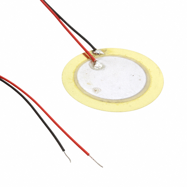
1 Piezo Element
4 10K Resistor
1 470 Ohm Resistor
1 NPN Transistor
1 33 µF Polarized Capacitor
1 10nF Non-Polarized Capacitor
1 Red 5mm LED
1 NE555P Timer IC
The project’s simple and flexible nature allows the easy substitution of different development boards for the Arduino to accommodate other setups. Similarly, tweaking the passive component’s values allows for generating longer or shorter output pulses if necessary.
Understanding the Basic Glass-Break Sensor Circuit
The circuit is based around a standard 555 timer IC running in monostable mode. This mode is often also called one-shot mode since the timer IC generates a single pulse of predictable duration when its trigger pin is pulled low. The accompanying passive components determine the generated pulse length. This project uses commonly available values of 10K for the resistor and 33µF for the capacitor, resulting in roughly one-third of a second output pulses with each trigger event. You can use this handy online calculator to experiment with different values and see how they affect the generated pulse duration.
However, the exact duration does not matter much in this project since the Arduino on the receiving end of the output pulses only detects rising edges. The main idea behind using the 555 timer IC is not to generate precise pulses but to make the piezo element’s output more deterministic and predictable.
This image depicts the project being assembled in an online circuit simulator. It shows how the 555 timer produces predictable output waves whenever it is triggered.
Piezoelectric components translate physical vibrations into electrical voltages and vice versa. For example, piezo-beepers can vibrate to produce signals that can produce an audible single-frequency tone. Conversely, these components can also translate vibrations to an electrical voltage. However, the produced signal is often not clean enough to reliably trigger an alarm or other parts of a circuit. Further, the produced currents are usually not significant enough to result in predictable and reliable input detections.
The NPN transistor in this project’s circuit acts as a switch that pulls the 555 timer’s trigger pin low whenever the piezo element outputs a voltage. The transistor effectively inverts and amplifies the signal, resulting in more predictability. The 555 timer generates an even more predictable output pulse that ultimately triggers the alarm.
These measures help ensure that real alarms are not missed because the generated signal is not strong enough. Conversely, electrical noise from the piezo element does not lead to frequent false alarms.
This schematic diagram depicts the project’s circuit. Scheme-it link
In this project’s schematic diagram, C2 and R3 configure the timer IC’s output pulse width. R1 and R4 are external pull-down resistors that ensure that input pins are not left floating. Similarly, R2 guarantees that the 555 timer’s reset pin is constantly pulled high to keep the IC from resetting. Finally, R5 is a simple current-limiting resistor for the red LED, which flashes briefly with each output pulse of the timer IC.
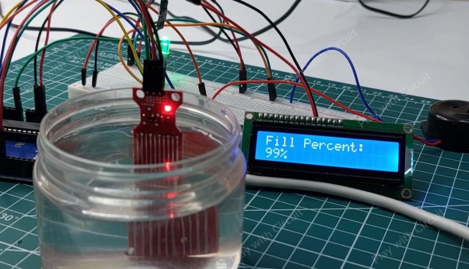
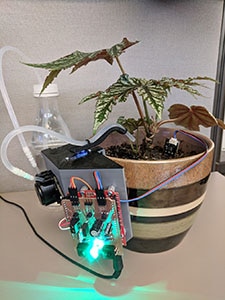
You can omit the LED and its accompanying resistor, but I found them helpful for debugging. Similarly, assembling the project on a breadboard and experimenting with different resistor and capacitor values was very valuable. I recommend taking this extra step to test whether the piezo element behaves as expected and how strong the vibrations need to be to trigger an alarm.
This image shows the project assembled on a breadboard and supplied by a standard 3V coin cell battery. The LED simulates the Arduino, and the push button triggers the timer without using the piezo element.
Connecting the Sensor to the Cloud
The Arduino SBC employed in this project receives the 555 timer’s final output and triggers the alarm if necessary. Connecting the development board to the Arduino IoT Cloud platform is a breeze, and the process only requires a few straightforward configuration steps. Using the Arduino IoT Cloud offers an online dashboard that allows the alarm status to be tracked from anywhere in the world, and it also lets the Arduino interface with smart home systems to take further action when it detects an alarm. Newcomers to the Arduino IoT Cloud should take some time to check out this introductory article that explains the steps for getting the Arduino online in great detail.
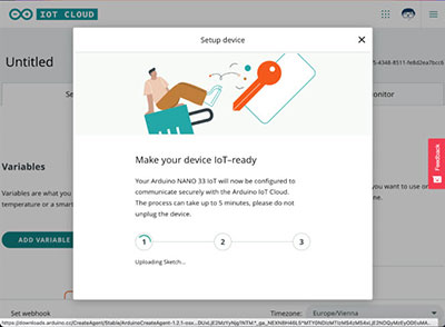
Once you have the Arduino connected to the cloud platform, add a new thing to the project. Then, add two boolean variables to the newly created thing. Set the update policy of both variables to “On Change.” Then name the first one “resetRequested” and ensure it’s writable. Users will later set this variable via the online dashboard to let the Arduino know it should reset a previously triggered alarm. The second boolean variable, “vibrationTrigger,” can be read-only. The Arduino will use it to inform the dashboard that the alarm has been triggered. The cloud platform can then display a warning on the web dashboard or perform further steps, such as turning on the lights in a room.
Create a new thing and add variables, as shown in this screenshot. Remember to enter your local network’s credentials.
Next, create a simple dashboard for the glass break sensor system containing a status label and a push button. Link the status label widget to the previously created “vibrationTrigger” variable. Then, add a push button widget to let users reset the alarm. Link the button widget to the “resetRequested” boolean variable from before and arrange the items to your liking:
This screenshot shows a simple Arduino IoT Cloud dashboard for tracking the glass break alarm state and resetting a previously triggered alarm.
Making the Arduino Push and Receive Cloud Updates
Once everything’s set up in the Arduino IoT Cloud, it’s time to make the Arduino react to the 555 timer’s output and communicate status updates to the cloud dashboard. To get started, navigate to the thing’s auto-generated sketch in the IoT Cloud web IDE and add the following variables to the top of the main code file:
#define TRIGGER_PIN 3

unsigned long lastUpdate = 0UL;

volatile boolean resetTriggered = false;
volatile boolean triggerReceived = false;
The define preprocessor statement contains the GPIO pin number connected to the 555 timer IC’s output pin. The lastUpdate variable is used within the loop method to wait a few milliseconds between status updates, and the volatile boolean variables are used within the interrupt and cloud callback functions.
The trigger input pin of the Arduino needs to be configured as an interrupt pin in the setup function using the following two lines of code:
pinMode(TRIGGER_PIN, INPUT_PULLDOWN);
attachInterrupt(digitalPinToInterrupt(TRIGGER_PIN), onTriggerReceive, RISING);
These lines ensure that the pin is an input connected to an internal pull-down resistor, keeping the pin low when not triggered by the 555 timer. The attachInterrupt call results in the Arduino calling the onTriggerReceive function whenever the 555 timer pulls the trigger pin high. The onTriggerReceive ISR (interrupt service routine) is basic, and it only sets the previously mentioned volatile triggerReceived flag:
void onTriggerReceive() {
  triggerReceived = true;
}
Interrupt handlers should be as short and fast-returning as possible to ensure that subsequent events are not blocked. For this reason, the ISR only sets a single flag that is then further processed within the loop method. Similarly, the onResetRequestedChange function, generated by the Arduino IoT Cloud, also just sets the other volatile boolean flag:
void onResetRequestedChange()  {
  resetTriggered = true;
}
The code’s loop function then checks whether these flags are set, and it performs certain actions based on their state:
void loop() {
  // Update Arduino Cloud data
  ArduinoCloud.update();

  unsigned long currentMillis = millis();

  if (lastUpdate - currentMillis >= 500) {
    if (resetTriggered) {
      vibrationTrigger = false;
      triggerReceived = false;
      resetTriggered = false;
      Serial.println("Alarm reset!");
    } else {
      vibrationTrigger = triggerReceived;
    }
    lastUpdate = currentMillis;
  }
}
The program pushes an update to the ArduinoCloud in each loop iteration before obtaining the current millis value. The code uses this value to check whether enough time has elapsed since it last inspected the two boolean flags. It waits approximately half a second between checks to help free up some CPU time for other tasks running in the background. If enough time has elapsed, the code inspects whether users requested a reset via the web interface, and it resets the alarm state if the “resetTriggered” flag is set. If no reset was requested, the program communicates the alarm state to the web interface.
Testing the Sensor
You can use the Arduino IoT Cloud’s online IDE to upload the program code to the Arduino once you’re done implementing the firmware for this project:
Use the highlighted buttons in the Arduino IoT Cloud web IDE to compile and upload the Arduino sketch.
Once the upload finishes, you can navigate to the newly created dashboard to test the sensor and reset functions. Tap the sensor to simulate strong vibrations, and the label on the dashboard should then flip and show that the alarm got triggered. Clicking the reset button to its left should change the label back to “false.”
The web UI informs you about the alarm state and allows you to reset a previously triggered alarm from anywhere in the world.
Summary
This article explains how to build a simple glass break sensor and connect it to the Arduino IoT Cloud. The sensor is based on commonly available and cost-effective components. A piezoelectric element translates physical vibrations into an electrical voltage that switches a transistor. The transistor acts as an inverter and as an amplifier that pulls the trigger pin of a standard 555 timer to a low state. The timer IC is configured to operate in monostable mode, which outputs a single predictable high pulse whenever triggered. The output waveform feeds an interrupt pin on the Arduino board, ultimately triggering the alarm.
The Arduino is connected to the Arduino IoT Cloud platform and communicates with the online service via two boolean flags. One flag allows resetting the alarm, and the other transmits the alarm state to the web dashboard. With this dashboard, users can inspect the alarm state from anywhere in the world. Additionally, the IoT Cloud service allows the Arduino to interface with other smart-home devices to trigger subsequent actions, for example, turning on the lights in a room or sending out a message in reaction to the alarm.