Mfr Part # A000066
ARDUINO UNO R3 ATMEGA328P BOARD
Arduino
License: General Public License LED / Display Drivers Oscilloscope Signal Generator Arduino
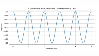
In this simple tutorial, we’ll learn how to create a frequency sweep using Arduino and Visuino. The frequency will smoothly sweep from 1Hz up to any desired frequency in 0.1Hz increments, all easily adjustable through visual programming.
Watch the Video!


Visuino software: Download here
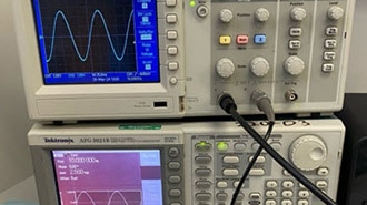
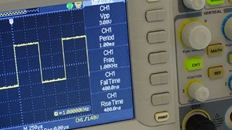
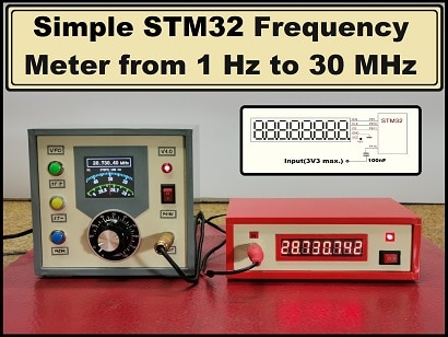
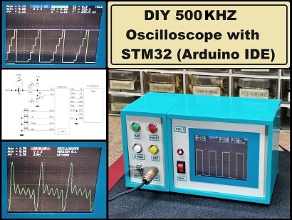
[Optional] An oscilloscope or frequency meter to see the signal like this one


The Visuino: https://www.visuino.eu also needs to be installed. Download the Free version or register for a Free Trial.
Start Visuino as shown in the first picture. Click on the "Tools" button on the Arduino component (Picture 1) in Visuino. When the dialog appears, select "Arduino UNO" as shown in Picture 2


If you want increments to be faster or slower than every second, select "ClockGenerator1" and change the frequency
Set the Starting Frequency: Select "AnalogValue1" and in the properties window set "Value"; in our case, it is 1Hz
Set the Frequency increments: Select "IntegerToAnalog1" and in the properties window set "Scale", in our case it is 0.01
Set the End Frequency: Select "CompareValue1" and in the properties window set "Value" in our case it is 5Hz and set "Compare Type" to ctSmaller
Select "PulseGenerator1" and in the properties window select "Frequency" and click on the pin Icon button and select "Float SinkPin"
Connect "ClockGenerator1" pin [Out] to "Counter1" pin[In]
Connect "Counter1" pin[Out] to "IntegerToAnalog1" pin[In]
Connect "AnalogValue1" pin[Out] to "Add1" pin[0]
Connect "IntegerToAnalog1" pin[Out] to "Add1" pin[1]
Connect "Add1" pin [Out] to "AnalogMultiSource1" pin[In]
Connect "AnalogMultiSource1" pin[0] to "AnalogSwitch1" pin [In]
Connect "AnalogMultiSource1" pin[1] to "CompareValue1" pin [In]
Connect "CompareValue1" pin[Out] to "AnalogSwitch1" pin [Enable]
Connect "AnalogSwitch1" pin [Out] to "PulseGenerator1" pin[Frequency]
Optional Connect "AnalogSwitch1" pin [Out] to "Arduino" Serial pin[In]
Connect "PulseGenerator1" pin[Out] to "Arduino" digital pin[2]

In Visuino, at the bottom, click on the "Build" Tab, make sure the correct port is selected, then click on the "Compile/Build and Upload" button.
If you power the Arduino module and connect a Frequency meter to the Arduino digital pin 2, you will be able to see the frequency increasing.
You will also be able to see the frequency increasing in the serial monitor window.
Congratulations! You have completed your project with Visuino. Also attached is the Visuino project that I created for this project. You can download it and open it in Visuino: https://www.visuino.eu
Download Visuino file: freq-sweep3.visuino