Why Do Passive Oscilloscope Probes Have So Many Ground Connection Options?
Most oscilloscopes come with a set of passive probes intended for general purpose applications. These probes generally include an accessory kit with a number of connection options (Figure 1).
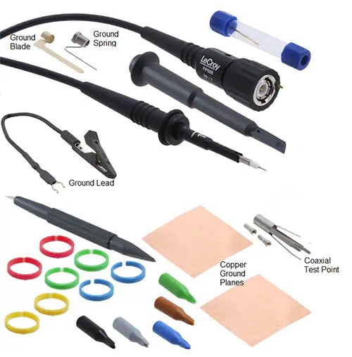 Figure 1: A typical accessory kit for a passive, high-impedance oscilloscope probe provides multiple connection options. (Image source: Teledyne LeCroy)
This figure shows the Teledyne LeCroy model PP008-1 high-impedance passive probe with the supplied accessories. Most manufacturers include similar connection devices. You might wonder why there are so many devices included to connect the probe to ground. The answer is that the ground connection has a big effect on high-frequency measurements, so the devices that come with the probe help ensure the best possible ground connection.
The circuit model of a typical 500 megahertz (MHz) X10 probe includes resistance, capacitance, and inductive elements (Figure 2).
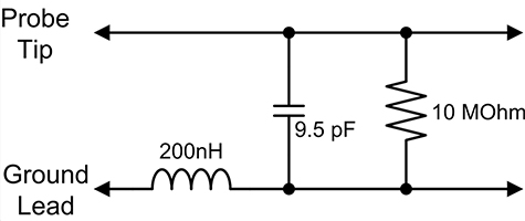 Figure 2: The circuit model of a 500 MHz X10 passive probe includes the ground lead inductance along with resistance and capacitance. (Image source: Art Pini)
From the measurement point, the probe looks like a 10 megaohm (MΩ) resistor in parallel with a 9.5 picofarad (pF) capacitor. The ground side includes the series inductance of the ground connection. For a typical 4.5 inch (in.) (11.4 centimeter (cm)) ground lead, the inductance amounts to about 200 picohenries (pH).
At frequencies below about 20 MHz, the ground lead inductance doesn’t have much effect. The 10 MΩ resistance can basically be ignored, and the inductor (L) and capacitor (C) form a series LC circuit with resonance at 115 MHz. The effect of the inductance is to cause peaking in the probe response so that high-frequency components of any signal are amplified. Ideally, the ground lead shouldn’t be used for signals having frequency components above 20 MHz.
So, how do I connect the probe to use the full bandwidth? The idea is to use a connection method that minimizes the lead inductance. The ground spring shown at the top of Figure 1 is a good solution. The probe tip connects to the measurement point, while the ground spring is connected to the nearest circuit ground point. Just make sure that you insert the spring so that the coiled portion is completely shorted by the probe’s ground ring.
Slightly lower inductance is achieved by using the ground blade. The flat metal of the blade offers less inductance than the cylindrical wire cross-section of the ground spring. Using a foil ground plane attached to the circuit ground makes it easier to connect the ground blade to a good ground (Figure 3).
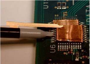 Figure 3: The ground blade connects to a copper foil ground plane soldered to the ground pins on the IC. (Image source: Teledyne LeCroy)
In this example, a Teledyne LeCroy PP007-WR-1 passive probe uses the ground blade to ground the probe to a copper ground plane soldered to the ground pins of the IC. An IC probe cover guides the probe tip to the IC test point pin, while the insulated extension fits between the IC pins and provides stability.
The next obvious question is: what difference do each of these ground connections make in the measurement? Let’s compare some. Figure 4 shows four overlaid measurements of a pulse with 750 picosecond (ps) transition times (signal bandwidth of approximately 466 MHz). Each measurement uses a different grounding technique.
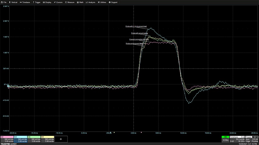 Figure 4: Comparing the measured response to a narrow pulse with sub-nanosecond transition times. The red trace was acquired using a coaxial connection and is the reference signal here. (Image source: Art Pini)
The red trace is the signal acquired using a coaxial connection and serves as a reference standard. The blue trace was acquired using a standard 4.5 in. (11.4 cm) ground lead. Note that the high series inductance of the lead causes a large overshoot. The green trace is the response using a ground spring. This response is certainly better than that of the ground lead. The yellow trace is the response of the ground blade and is only slightly better than the ground spring.
Conclusion
When using high-impedance passive probes for measuring signals with frequency components above 20 MHz, you should use the shortest possible ground lead. That’s why there are so many options included in the probe accessory kit.

Have questions or comments? Continue the conversation on TechForum, DigiKey's online community and technical resource.
Visit TechForum


