Basic Oscilloscope Probe Repair: Replacing Damaged Probe Pins
How many broken oscilloscope probes do you have in your lab? Of those probes, how many have broken or damaged pins? I’ll bet it’s a large percentage. Damaged pins are the number one cause of oscilloscope probe failures. It’s easy to understand why. You can put a lot of pressure on the pins when probing, whether trying to break through a solder mask or hold the contact on the printed circuit board (pc board) while you’re juggling the oscilloscope controls, forgetting how much pressure you’re actually applying. Not to mention the classic: probes hanging from the oscilloscope and resting tip down on the floor—just waiting for someone to step on them. Poof, broken probe.
Happily, most oscilloscope probes with broken or bent probe tips can be easily repaired. Probe suppliers generally provide a replacement pin in the probe accessory kit. If you need more than one, they are also available through DigiKey for a wide range of probe models.
There are two types of probe pins commonly used, press-fit pins or pins with threaded bodies. Press-fit pins are available in either rigid body or spring-loaded forms. Let’s look at some common probes, the pins that they use, and how they are replaced.
Let’s start with a common third-party replacement probe, the Cal Test Electronics CT2674A. This is a switchable 1:1 or 10:1 passive probe with a bandwidth of 100 megahertz (MHz) (Figure 1).
 Figure 1: The CT2674A probe shown with the accessories that come with it, including a replacement threaded tip. (Image source: Cal Test Electronics)
The tip has a threaded black plastic body and is available as Cal Test Electronics CT2711A-0 (Figure 2).
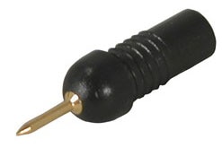 Figure 2: A black threaded replacement pin for the CT2674A probe is shown. It is also available in grey. (Image source: Cal Test Electronics)
The threaded body probe pins are the easiest type to replace; the old pin is removed from the probe by grabbing the pin body with your finger and turning counterclockwise to remove the right-hand threaded pin body. The replacement pin is screwed into the probe by turning in the clockwise direction (Figure 3).
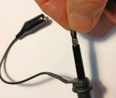 Figure 3: Threaded body pins are removed by turning the damaged pin body counterclockwise. The replacement pins are inserted and tightened by turning in a clockwise direction. (Image source: Art Pini)
Remember that these are plastic parts and should be hand tightened. Do not use pliers or other tools as you risk stripping the plastic threads.
The Teledyne LeCroy PP007-WR-1 is a 500 MHz, 10:1 passive probe which uses push-on pins. As mentioned previously, the pins are available in two types. The PP007-004 is a rigid-body pin, while the PP007-005 is a spring-loaded pin (Figure 4).
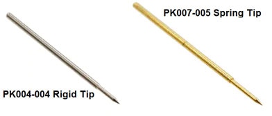 Figure 4: Examples of both rigid body and spring-loaded probe pins. (Image source: Teledyne LeCroy)
Both pins have a diameter of 0.5 millimeters (0.0197 inches) and fit into the probe body’s socket.
A damaged probe tip can be removed by grabbing the pin at the widest part with a pair of long-nose pliers and pulling gently along the pin’s long axis until it comes out of the socket (Figure 5).
 Figure 5: Removing the pin of the PP007-WR-1 probe by pulling along the pin’s long axis. (Image source: Art Pini)
Insert the replacement pin by using long nose pliers to grasp the pin shoulder and gently push it into the probe socket until it bottoms.
Once the pin is replaced you should verify that the probe is working and perform low-frequency compensation according to the probe or oscilloscope’s user manual. That’s all there is to it.
Conclusion
An ounce of prevention is worth a pound of care when it comes to oscilloscope tips. However, when the inevitable does happen, whether due to overly zealous probing or accidental “foot” pressure, probe tips are easily replaced. A quick compensation check, and you’re back up and running.

Have questions or comments? Continue the conversation on TechForum, DigiKey's online community and technical resource.
Visit TechForum


