Victorian Clock Display: 350 LEDs and One Control Board to Rule Them All
In a previous blog, “Recreating 21-Segment Victorian Displays”, I discussed how my do-it-yourself (DIY) chum (and Maker extraordinaire) Steve Manley and I are in the process of creating modern interpretations of 21-segment Victorian displays. As opposed to using the small incandescent light bulbs that illuminated the original display, we’re using tricolored WS2812B LEDs, such as the 4684 from Adafruit Industries LLC.
Similarly, instead of using a complicated electromechanical switch to control everything, which would have been state-of-the-art “back in the day,” we’re using a modern microcontroller unit (MCU), which would have been mindboggling to Victorian engineers and inventors.
Steve and I are both creating 10-character displays. Just to give you an idea of what one of these looks like, Figure 1 shows an early implementation of Steve’s display using a 3D printed front panel sprayed with brass-colored paint. In this case, Steve is running a simple test pattern to check that all of his LEDs are functioning.
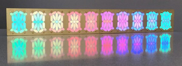 Figure 1: Early 10-character implementation of modern interpretation of 21-segment Victorian displays. (Image source: Steve Manley)
You will observe that Steve’s pseudo-brass panel is split into two halves because his 3D printer couldn’t handle the full 20-inch (in.) span of the display. Also, Steve opted for 10 large “holes” in his front panel surrounding the outer edges of his characters. By comparison, my front panel was laser cut out of a single piece of acrylic with a brass finish (Figure 2).
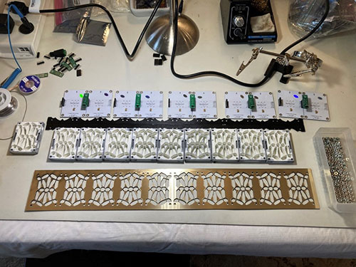 Figure 2: The main elements of the 10-character display. The laser-cut acrylic pseudo-brass panel is seen in the foreground. Behind this panel are ten 3D printed shells, each 64 mm tall, 50 mm wide, and 10 mm thick. At the top are ten LED boards seen from the back, grouped as five two-board sub-assemblies. (Image source: Max Maxfield)
Each of the circuit boards is 50 mm wide and 64 mm tall. These boards are grouped into five two-board sub-assemblies. There are also ten 3D printed shells that are the same size as the boards and 10 mm thick. In the case of my laser-cut pseudo-brass panel, the laser was capable of cutting out the 21 segments forming each character, leaving thin 0.7 mm strips between the segments.
Steve and I have worked on similar projects in the past, usually by way of friendly competition, like the cunning chronographs we created a couple of years ago (see, Create a Cunning Chronograph with Arduino). The thing is that, although we’ve previously agreed on ground rules, like the number and relative locations of the LEDs, we’ve typically gone our own way with regard to things like MCUs, real-time clocks (RTCs), and such. The problem with this approach is that it’s made it close to impossible for us to share and exchange code.
Furthermore, every time we start work on a new project, we both end up “reinventing the wheel,” which is a waste of time and effort. Thus, in this case, we determined to create a single control board that we would both use to drive our displays. Additionally, we decided to create a board with all the “bells and whistles” necessary to power future projects for years to come.
Meet our Victorian Display control board
After much brain-stem-storming, negotiating, and compromising, we came up with a design that addressed all of our needs. Perhaps the best way to go about this is to show you the board (Figure 3) and then take a brief stroll through the various parts.
In the middle of the left-hand side we have the main processor, which is a Teensy 3.6 in the form of a DEV-14058 from SparkFun Electronics. It features a 32-bit Arm Cortex-M4F processor running at 180 megahertz (MHz) (it can be overclocked to 240 MHz) with 1 megabyte (Mbyte) of flash, 256 kilobytes (Kbytes) of SRAM, and 4 Kbytes of EEPROM.
 Figure 3: The first version of our control board, starting with the DEV-14058 Teensy 3.6 processor board—based on an Arm Cortex-M4F core—on the left. (Image source: Steve Manley)
Behind the Teensy on the far side of the board are two potentiometers that can be used to control whatever we desire, such as the brightness of the display or sensitivity to sound. To the right of the Teensy are headers that provide access to the MCU’s uncommitted input/output (I/O) pins.
In front of the Teensy is a CR2032 coin cell battery that’s used to maintain the RTC when main power is removed from the system. In front of the CR2032 to the right are headers that allow additional I2C-based sensors and actuators to be connected to the board. In front of the CR2032 to the left are eight three-pin header groups, each comprising a 0 volt pin, a 5 volt pin, and a data pin. Each of these can drive a string of WS2812 LEDs. Also, the Teensy has an associated Octo LED Library that can drive eight strings simultaneously.
In the case of our 21-segment displays, the seven shorter segments each have a single LED, while the fourteen longer segments each have two LEDs, resulting in 35 LEDs per character, giving a grand total of 350 LEDs for the 10-character display. Each LED requires 24 bits of data, and the clock used to load the LEDs runs at 800 kilohertz (kHz). This means that if we were to drive all of the LEDs from a single MCU pin, it would take ((35 x 10) x 24)/800,000 = 10.5 milliseconds (ms) to load the chain.
By comparison, using the Teensy’s Octo library and by partitioning our 10 characters into five two-character pairs, we can reduce this time to only ((35 x 2) x 24)/800,000 = 2.1 ms. Even better, the Octo library can use the Teensy’s direct memory access (DMA) engine to perform this upload in the background, thereby freeing the main processor to perform other tasks, like calculating our amazingly cunning lighting effects.
The five momentary pushbutton switches in the middle of the board are used to access menus, select modes and effects, and enter values (e.g., date and time). It’s also possible to connect five cabinet-mounted switches in parallel using the green screw-block terminals mounted on the edges of the board. We also decided to include infrared (IR) control capability that can be used to perform the same tasks as the pushbuttons. The IR detector is located below the middle button. Above this button is a light-dependent resistor (LDR) that can be used to control the display’s brightness based on ambient light. Above the LDR there’s an Electret microphone, which we can use to cause the display to respond to sound. All of these devices can be removed from the board, mounted on the cabinet, and connected to the board via the green screw-block terminals.
On the right-hand side of the board, we see a102010328 Seeeduino XIAO from Seeed Technology. Although it’s only the size of a postage stamp, the XIAO packs a punch with an ATSAMD21G18 32-bit Arm Cortex-M0+ processor core running at 48 MHz with 256 Kbytes of flash memory and 64 Kbytes of SRAM. The XIAO is used to process any IR control signals and feed them to the Teensy. Although this might be considered to be overkill (because we could almost certainly use the Teensy to handle the IR directly), we decided that a “divide-and-conquer” approach would make our lives a lot easier in the long run.
Any surface mount devices (SMDs) are located under the board. These include a DS3231SN# RTC from Maxim Integrated, an SGTL5000XNAA3R2 low-power stereo audio codec from NXP, an LS119-S switch debounce chip from LogiSwitch, and a 74HCT245 octal bus transceiver acting as a voltage level shifter from Toshiba Electronic Devices and Storage Corp.
The red control board is shown mounted on the back of my display in Figure 4. Also shown is a green power distribution board, which includes a robust 3.3 volt regulator that can be used to drive any additional 3.3 volt sensors if required.
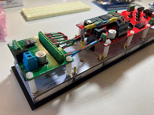 Figure 4: Assembling a 10-character display. The red control board is shown on the right of the image. The green board on the left is used to distribute power to the boards and displays. (Image source: Max Maxfield)
On the right of the display, not shown here, is a blue prototyping board. All of this means that we have red, green, and blue (RGB) boards, which “tickled our sense of humor.” Ideally, the power distribution board would have been red while the control board would have been green—but for reasons unknown—the board fab would have imposed a significant cost penalty for us to have the thicker copper required for power distribution on a red substrate, so we did what we had to do to save money.
Programming the control board
The next step is where the real fun starts because we have to start writing the code to drive the display. One approach we plan on using is to have the concept of a background color, a foreground color, and a mask. When a mask bit is set to 0, the corresponding segment will display the background color; when the same mask bit is set to 1, that segment will display the foreground color. The interesting point here is that both the foreground and background colors could be static colors like black, white, or some other color. Alternatively, either or both the foreground and background colors could be dynamic, such as rainbow stripes rippling across the display, for example.
Conclusion
There are many other experiments we intend to perform using these newly minted Victorian clock displays. For example, using the microphone and the audio codec chip, we could have an audio-reactive mode (see also Audio-Reactive Artifact with Arduino Part 1 and Part 2). Another thing I’d like to try is adding the ability for me to cause scrolling text to “slide” across the display by my tilting it to the left or right (see also Adding Motion and Orientation Sensing to Hobby Projects).
In closing, I keep on thinking about George Lafayette Mason who applied for the patent for the original 21-segment displays in 1898, which is 123 years ago as I pen these words. I wonder what George would have thought if he could see what we are doing with his idea using the technologies of today.

Have questions or comments? Continue the conversation on TechForum, DigiKey's online community and technical resource.
Visit TechForum


