The Case for Direct Port Manipulation
As programming becomes more and more accessible to the masses, some basic but valuable bits of code may fall by the wayside or perhaps be forgotten altogether, such as direct port manipulation (DPM). Some programmers argue that these commands are hard to read and can be confusing to neophytes, and so should never be mixed with more familiar structures. Why not use all the tools available to keep code concise and efficient?
For example, each port of an 8-bit microcontroller requires three, 8-bit registers to control port activity. These registers are the DDRx for input/output direction, the PORTx for pin logic level control, and the PINx which holds the current pin states of the port. To elaborate, let’s look at port C. During setup, a programmer may want to set the port C pins as outputs with an initial LOW state. Frequently, a tidy “for loop” is written requiring 3 or 4 lines of repeating code that steps through the pins from zero to seven for a total of 32 lines of written code executed. Using library functions inside the loop such as pinMode() and digitalWrite() invokes more “behind the scenes” activity resulting in a multitude of additional executed code.
Ultimately, the eight direction register bits for port C (DDRC) are set HIGH and the eight logic level register bits for port C (PORTC) are set LOW. The exact same action can be accomplished by setting the bits HIGH or LOW with the following direct port register commands;
DDRC = 0xFF; //Set port C pins as OUTPUTS (in binary DDRD = 0b11111111;)
PORTC = 0x00; //Set port C pins LOW (in binary PORTC = 0b00000000;)
How about setting port A as inputs?
DDRA = 0x00; //Set port A pins as INPUTS (in binary DDRA = 0b00000000;)
And finally, port D as mixed input and output:
DDRD = 0x0F; //Set the port D upper four bits as INPUTS and the lower as OUTPUTS (in binary DDRD = 0b00001111);
Using a hexadecimal value like 0xFF adds an interesting insight into understanding the bit value assignment in the register. With “0x” being the hexadecimal indicator, the first number ‘F’ represents the upper four bits of an 8-bit register and the second number ‘F’ represents the lower four bits.
All possible combinations of bits set HIGH or LOW can be represented by a hexadecimal or binary literal (number). Using binary literals is more visual as all eight bits can be seen as the code is written. Either is acceptable if supported by the compiler, however hexadecimal is shorter and looks cool.
Note: Using binary literals is not a universal standard in C/C++.
Let’s take this a step further
With ports A and C configured in setup, only a few lines of additional code using DPM in the main loop are required to read digital devices and operate other digital devices. In practice, two stepper motors with travel limit switches controlled by a digital joystick are easily programmed with a minimal number of register commands and a lookup table. The hardware setup for this scenario is illustrated in Figure 1.
 Figure 1: Joystick/stepper motor hardware setup with microcontroller ports A and C highlighted. (Image source: DigiKey)
Hardware:
A single digital joystick with its four normally open (NO) contacts connected to VCC are also connected to pins 0 through 3 of port A. The outputs are pulled LOW at the microcontroller. When the contacts close, the port pins go HIGH. The contacts represent UP, DOWN, LEFT, and RIGHT control and are configured to allow two adjacent contacts to activate at the same time, resulting in eight possible switch output combinations. A ninth output represents ALL STOP which occurs when the joystick is centered, and all the contacts are open.
Four limit switches with their NO contacts connected to ground are also connected to the remaining pins of port A corresponding to the joystick UP, DOWN, LEFT, RIGHT configuration. The switch outputs are pulled HIGH at the microcontroller. When the contacts close, the pins go LOW.
Stepper motor driver boards create mechanical motion by toggling three control pins high and low to facilitate step, direction, and hold functionality. For this example, all eight bits of port C are dedicated to operating two drivers even though two pins are not used.
Programming:
To generate the correct output to the drivers, a lookup table is used to translate the four joystick bits to the eight driver bits. A single line of code in the main loop calls the function ‘get_output()’ and passes the contents of the PINA register into the function. The value returned from the function is written directly to the PORTC register;
PORTC = get_output(PINA);
Within the function, the lookup table ‘lookup_output[ ]’ is accessed and an indexed value is returned. But there is something else going on inside this function that involves the limit switches. The lookup table index value contained within the square brackets of ‘lookup_output[ ]’ is represented by a bit shifting and masking expression. The resulting index variable is the bitwise AND of the upper 4 bits of the input register (limit switch values) and the lower four bits (joystick values). If any of the limit switch contacts are closed and a zero value exists in any of the four upper bits, the corresponding lower bit is cleared.
Note: As four bits can represent 16 unique bit combinations, the seven lookup table index positions that are not used are translated to 0x00 to prevent errors.
Copyuint8_t get_output(uint8_t porta_val)
{
  return lookup_output[(porta_val >> 4) & (porta_val & 0x0F)];
}
Example:
The joystick, in the UP and RIGHT position with all limit switches open would result in a binary PINA register value of 0b11111001 (or 0xF9 hex) passed to the function. The function zeros out the upper four bits using a bitwise AND of 0b00001111 (0x0F) which results in 0b00001001 (0x09) as the lookup table index value. Comparing this result using another bitwise AND with the shifted limit switch state value 0b00001111 (0x0F) leaves the previous value unchanged returning 0b00001001 (0x09) as the final index value which points to 0b00100001 (0x21) in the lookup table. This is the stepper driver translation for UP and RIGHT. See Figure 2.
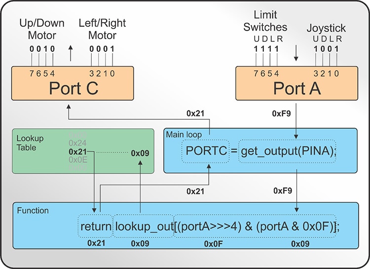 Figure 2: Microcontroller interpretation of Port A and Port C inputs when joystick is in the UP and RIGHT position. (Image source: DigiKey)
If the UP limit switch had been reached resulting in a zero bit, the shifted value would be 0b00000111 (0x07) rather than 0b00001111 (0x0F) which would negate the corresponding UP joystick value resulting in a final index value of 0b00000001 (0x01) rather than 0b00001001 (0x09). The translated value for 0b00000001 (0x01) is 0x26 in the lookup table. This is the stepper driver translation for RIGHT only. See Figure 3.
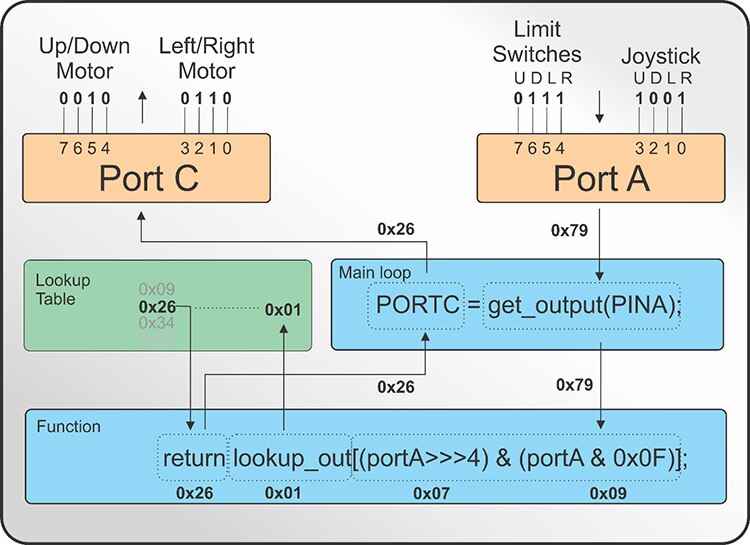 Figure 3: Microcontroller interpretation of Port A and Port C inputs when joystick is in the UP and RIGHT position while the UP limit switch is tripped. (Image source: DigiKey)
Conclusion
Whether or not a programmer adopts DPM as a viable tool for configuring, reading, or writing port data, substantially minimizing code is a good motivator. The same operations using standard library functions require much more code and may take up a considerable amount of the available program memory. The code supplied below uses less than 1% of the memory of the ATMEGA328P microcontroller used in bench testing. Proper commenting of the code is key to understanding DPM functionality in written code and makes its use easier for any level of programmer to debug.
DigiKey Hardware Examples:
Stepper motors - https://www.digikey.com/short/pdnfp4
Stepper controllers - https://www.digikey.com/short/pdnf4r
Joystick - https://www.digikey.com/short/pdnf57
Limit Switches - https://www.digikey.com/short/pdnfwm
Sample Code:
Copyconst uint8_t lookup_output[16] = {
0x09,   //Index 0  All Stop. Apply hold current
0x26,   // Index 1 Right
0x34,   // Index 2 Left
0x00,   // Index 3 Unused
  	0x36,   // Index 4 Down
  	0x0C,   // Index 5 Down/Right
  	0x31,   // Index 6 Down/Left
  	0x00,   // Index 7 Unused
  	0x24,   // Index 8 Up
  	0x21,   // Index 9 Up/Right
  	0x0E,   // Index 10 Up/Left
  	0x00,   // Index 11 Unused
  	0x00,   // Index 12 Unused
  	0x00,   // Index 13 Unused
  	0x00,   // Index 14 Unused
  	0x00    // Index 15 Unused
};

void setup() {
     // Set all bits in port A direction register as INPUTs;
    // Limits (up, down, left, right) Joystick (up, down, left, right)
    DDRA = 0x00;

    // Set all bits of port C direction register as OUTPUTs;
   // Motor control (Not Used, Mot_1, Dir_1, En_1, Not Used, Mot_2, Dir_2, En_2
   DDRC = 0xFF;
}

void loop() {
    //Send the port A values to the function. Write the return value to port C.
   PORTC = get_output(PINA);
}


/***** Input Value Translation Function *******/
uint8_t get_output(uint8_t porta_val)
{
    // Compare the limit switch and joystick values. Retrieve and return the translated value.
    return lookup_output[(porta_val >> 4) & (porta_val & 0x0F)];
}

Have questions or comments? Continue the conversation on TechForum, DigiKey's online community and technical resource.
Visit TechForum


