Additive Manufacturing: From Prototype to Production
Contributed By DigiKey's North American Editors
2023-06-28
Additive manufacturing or AM is part of a wider trend towards digital manufacturing for fast prototyping cycles — and getting products into production more quickly.
Consider the prototype process after the mass adoption of 3D CAD but before the advent of 3D printing. Engineers employed 3D CAD to design parts but then exported the details to two-dimensional drawings. The latter were then read by machine operators who would program CNC (computer numerical control) machines to produce the parts. Today, digital manufacturing sends 3D part models directly to machines (whether CNC machine tools or 3D printers) for production. Fully automated algorithms drive the execution of these part builds. It’s a capability that greatly reduces delay between part design and part production.
Digital manufacturing also vastly increases the information available to engineers. In some cases, designs submitted to prototyping and batch manufacturing services via web portals can return instant manufacturability feedback and accurate pricing. So, multiple designs can be rapidly costed before prototyping even starts.
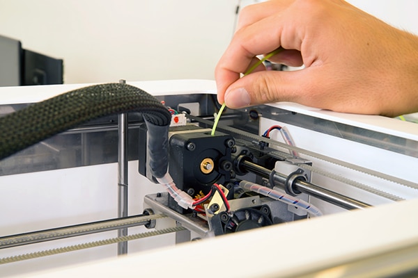 Figure 1: Additive-manufacturing machinery of all types (including that based on FDM as shown here) employ stepper motors for controlled and coordinated motion of the extrusion nozzle (or other deposition end effector) through 3D space. NEMA 17 stepper motors capable of torques to 60 oz-in. are common. (Image source: Dreamstime)
AM is core to such modern versions of iterative upfront design. Plus AM allows the production of part forms that are impossible using conventional machining — featuring hollow bone-like structures with internal lattices, for example. The ability to rapidly print thermoplastic components (and at low cost) can have a transformative impact on early prototyping. Such components may be used as the actual prototype parts or as tooling to fixture machined parts or mold composite parts. More recent developments allowing high-performance metal parts to be directly printed enable even more possibilities for prototyping, producing production tooling, and even directly manufacturing parts for low-volume production.
 Figure 2: Advanced motion control can minimize fluctuations of current sine waves into 3D-printer axis motors for quieter and smoother operation. For example, some standalone ICs to drive two-phase stepper motors drive motor step and direction use optimized chopper routines to maximize motion performance, motor torque, and efficiency. (Image source: Trinamic Motion Control GmbH)
Names for proprietary AM processes abound, but all processes fall into one of seven ISO-standard AM categories.
Material extrusion 3D printing: Material is selectively dispensed through a nozzle or orifice. Most commonly, thermoplastic polymer is the material being extruded and the process is commonly called filament deposition modelling or FDM. Almost all low-cost 3D printers and even many higher-grade machines use FDM.
Powder-bed fusion or PBF: Thermal energy such as that from a laser, electron beam, or plasma arc is focused to melt and fuse regions of powdered material contained in a powder bed.
In fact, the first form of powder bed fusion developed in the 1980s is called selective laser sintering or SLS. In contrast with certain techniques used today, SLS couldn’t fully melt powders … so fully dense parts couldn’t be produced. Now, modern powder bed fusion equipment fully melts metal powders to produce fully dense parts with grain structures comparable with those of wrought components. The mechanical properties of SLS-produced parts can be significantly better than those of cast components.
Vat photopolymerization: Liquid photopolymer in a vat is selectively cured by light-activated polymerization. This process is often called stereolithography.
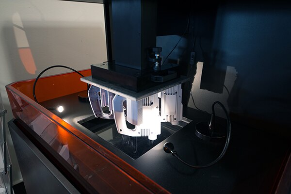 Figure 3: Stereolithography (SLA) and digital light processing (DLP) are additive manufacturing technologies used for creating models, prototypes, patterns, and production parts. (Image source: Dreamstime)
Directed energy deposition or DED: Thermal energy from a laser, electron beam, or plasma arc is focused to melt and fuse materials as they are being deposited. Wire feed or blown powder may be used as the feedstock.
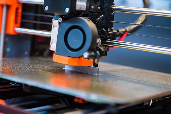 Figure 4: Round-rail linear guides and exposed synchronous belt drives are common on tabletop 3D printers as well as more sophisticated equipment. (Image source: Dreamstime)
Binder jetting (BJ) and material jetting (MJ): In BJ processes, a liquid bonding agent is selectively deposited to join powder materials. In contrast, in MJ processes, droplets of build material are selectively deposited using a process very similar to inkjet printing.
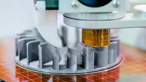 Figure 5: This 3D printer has a heavier end effector, so is built around a SCARA robot arm. (Image source: Dreamstime)
Sheet lamination: Sheets of material are bonded to form a part. This is the oldest additive process, with early machines layering and bonding paper profiles to create complex 3D parts similar to the way plywood is manufactured.
Commonalities between equipment for different AM types
All of the AM methods just described building 3D parts by the layering of 2D profiles — each on top of the last. In builds involving layers having significant overhangs or features that would detach, support structures are first deposited and then removed after the build.
While material-extrusion-based FDM is the dominant AM approach for everything from hobby-grade 3D printers to industrial prototyping in plastics, two processes are increasingly common for producing high-strength aerospace-grade metal components. These are:
- Powder bed fusion (PBF) for small and fully finished parts
- Directed energy deposition (DED) for larger parts which often require final machining
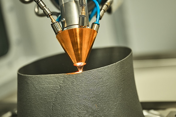 Figure 6: AM equipment used to produce advanced metal workpieces are servo systems employing advanced motion components and even direct-drive motors in some cases. Such builds allow operators to leverage the precision of laser-based build approaches. (Image source: Dreamstime)
As all types of AM processes have advanced, they’ve come to employ many of the same automation solutions. For example, a wide array of advanced automation components from Festo — including electromechanical linear actuators sporting ballscrew or belt drives — are found in FDM machines ranging from hobby-grade to professional equipment as well as highly sophisticated SLS equipment.
AM design freedoms and limitations
A significant advantage of AM parts over subtractive processes such as machining, is greater freedom to create different shapes. Machined features can only be created where the machine tool can place its cutter. This often limits the minimum radius of internal corners, makes certain overhanging features challenging, and means that internal voids are simply impossible to achieve with a single component. These limitations often result in structures assembled from multiple components bolted together, increasing manufacturing costs and weight while reducing strength and reliability. Freed from these limitations, parts produced using additive processes can often consolidate many components, greatly reducing cost while improving performance.
Generative design is a process in which algorithms design components by making many small changes and simulating the performance of different components in a process much like evolution. Resulting shapes typically have complexity far beyond anything a human designer would create … and are strikingly similar to the structures that nature has evolved.
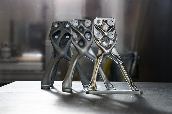 Figure 7: Structures created with generative designs are often associated with additive manufacturing, although they’re often produced via digital manufacturing and five-axis CNC machining. The NASA Evolved Structures program created the components shown here; the NASA team employed CNC machining as machined parts can be more capable than AM variations for very high-performance applications. That’s in part because (despite AM advances) machined components are subject to less variability in material properties. (Image source: NASA)
As components become increasingly complex, with organic external shapes and internal lattices and channels, digital models require more data. Operations such as rendering, slicing, support structure generation and machine code generation all become more difficult. The established tessellated file formats (which represent surfaces as meshes of planar triangles) are becoming cumbersome. One approach has been to allow mesh files with 3D curved triangles so that a smaller number of triangles can be used to approximate a surface.
A far more efficient way of representing such complex geometry is through the use of implicit geometry, although this is not yet compatible with most CAD software.
AM allows control over internal geometries
AM is unrivaled in its ability to create internal geometries. This capability enables otherwise impossible lightweight and high-strength structures with internal lattices similar to those of bones and plant stems. The capability also allows the design of consolidated parts with features such as internal ducts, pipes, manifolds, cooling channels or heat exchangers. While such components are conventionally machined and fabricated from pipes and plates, resulting in constant diameters and channel widths, with AM it is possible to vary the profiles. Features such as turbulators can be included which increase heat transfer.
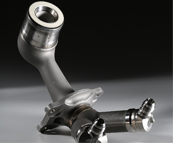 Figure 8: Shown here is GE’s Aero LEAP fuel nozzle. (Image source: GE)
Consider how AM aerospace components have been used on aircraft for many years. One of the best-known examples is the General Electric Aero LEAP fuel nozzle, which has been in production since 2015. This replaced 18 components with a single consolidated component having all the required complex internal channels.
Making further use of AM is the General Electric Catalyst turboprop engine that consolidates more than 800 conventionally manufactured parts into 12 AM parts. This engine is expected to be certified in 2023.
Laser beam powder bed fusion or PBF-L is the most established and mature AM metal process. This process is used to produce GE’s engine components and it can also produce high quality polymer components. The size of the build volume is limited to around 400 mm × 400 mm × 800 mm by the need to maintain a consistent gas flow over the build area as well as the cost of filling the bed with powder. Metal powders are heavy and also very expensive in the quality required for consistent fusion. Deposition rates for a single laser are up to 20 cm3/hour while systems with multiple lasers can achieve up to 150 cm3/hour for aluminum components. Good surface finish suitable for finished parts can be achieved. The surface quality depends on the particle sizes of the powder feedstock, with particle diameters as small as 5 µm.
The material properties of parts produced by powder bed fusion depends largely on the control of the melt pool, where the powder material is fused into the solid part. Controlling this melt pool is essentially the same as a welding operation, and the fundamental understanding builds on many years of welding research and development. Laser and electron beam welding have been used for more than 50 years while arc welding has been used for more than 100 years. This knowledge allows parts to be produced having highly refined grain structures, often comparable with the highest performing wrought components. However, process variability remains somewhat higher.
Conclusion
Although less common, other energy beams apart from lasers can also be used for powder bed fusion. Electron beam powder bed fusion has the advantage that the beam can be steered with magnets rather than requiring mechanically steered mirrors. This means somewhat higher build rates are achievable, but surface finish is not as fine as for laser-based processes.
At the other end of the technology spectrum, open-source 3D printers can be built at home and can even print their own components — essentially becoming self-replicating. Just a few automation components such as stepper motors must be bought; all the mechanical elements of the build can be made.

Disclaimer: The opinions, beliefs, and viewpoints expressed by the various authors and/or forum participants on this website do not necessarily reflect the opinions, beliefs, and viewpoints of DigiKey or official policies of DigiKey.


