Synchronous Rectifiers Improve Power Supply Efficiency—If Controlled Effectively
It is no secret that modern electronic devices with faster processors, more memory, and greater bandwidth require more power. At the same time, market demands press for smaller power supplies. Supplying higher power levels in smaller packages requires an increase in power efficiency. This increase in efficiency necessitates a reduction in power supply losses, which translates to a rethinking of their basic design.
Let’s take a look at where losses occur and what we can do about them. We’ll use a flyback power supply as an example (Figure 1). The flyback converter switches a field effect transistor (FET) on and off.
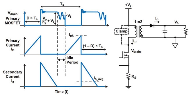 Figure 1 : A basic flyback power supply switches a FET on and off. Shown are its associated current and voltage waveforms. (Image source: Texas Instruments)
During the time the FET is on, the current (IP) flows in the primary of the coupled inductor. This builds the magnetic field in the inductor. When the FET is turned off, the secondary current (IO)—due to the collapsing field in the inductor—flows in the secondary, through the diode, to the output filter and the load. Losses come in the form of those found in the coupled inductor, dynamic switching, and conduction losses in the FET and the output diode, as well as the power lost in the clamp circuit. All of these losses should be evaluated, but in this post, we’ll focus on the conduction losses in the output diode.
When the output diode conducts, it exhibits a forward voltage drop (VF) which varies with the current level and temperature (Figure 2).
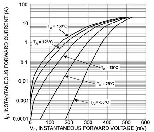 Figure 2 : The forward voltage drop of a typical Schottky diode varies with temperature and current. (Image source: Diodes Incorporated)
The forward voltage drop in this diode increases with increasing current and decreases with increasing temperature. For a forward current of 10 amperes (A) at 25°C, the forward voltage drop is about 420 millivolts (mV), meaning the diode is dissipating 4.2 watts. One way around this loss is to replace the diode with a FET that is switched on at appropriate times during the power supply’s switching cycle. This is a synchronous rectifier (SR), sometimes called an active rectifier. When the FET is on, its forward impedance is primarily the resistance (RDS(ON)) of the FET channel. The Texas Instruments CSD18532KCS is an N-channel FET with an RDS(ON) of about 5 milliohms (mΩ). Comparing this FET to the diode, we can see the advantages of the SR approach (Figure 3).
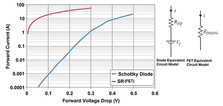 Figure 3 : A comparison of the forward voltage drops of the CSD18532KCS with a Schottky diode. The equivalent circuit models highlight the differences. (Image source: Texas Instruments)
The forward voltage drop for the FET at 25°C is only about 60 mV at 10 A forward current, compared to the 420 mV drop for the diode. The power loss is 0.6 watts compared to the 4.2 watts for the diode, which is quite a significant reduction in power loss and an improvement in the power efficiency of the power supply.
Texas Instruments did a comparison using the Texas Instruments UCC28740EVM-525 10 watt isolated output evaluation board. This evaluation module is a 10 watt off-line power module that provides constant-voltage and constant-current output regulation. It is based on a discontinuous conduction mode (DCM) flyback converter. In the test, they measured the forward voltage drop and current using super barrier rectifiers, and with SR using a Texas Instruments CSD19531Q5A N-Channel MOSFET (Figure 4).
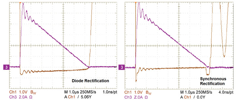 Figure 4 : Comparing the forward voltage drops and currents in the same power supply using diodes and MOSFET synchronous rectification. (Image source: Texas Instruments)
The difference in the forward voltage drops in the rectifiers is easily visible. The diode rectifier forward voltage runs a good fraction of a volt while the SR is much smaller. The small rectangular pulses at the beginning and end of the SR conduction phase are due to body diode conduction in the FET. These pulses do increase the conduction losses, but due to their short duration, they have little effect on the power supply efficiency.
The efficiency of the power supply over a range of load currents shows the advantage of the synchronous rectifier over more conventional diode rectifiers (Figure 5).
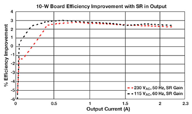 Figure 5 : Comparing the efficiency of the power supply over a range of load currents and source voltages shows a 2 to 3% improvement in efficiency. (Image source: Texas Instruments)
The efficiency of the synchronous rectification is 2 to 3% higher than that of the diode rectifier over a wide range of load currents. The increased complexity of the SR implementation can be well worth the cost.
Implementing synchronous rectification
The downside of SR is the need to drive the FET synchronously with the power supply switching operations. There are basically two approaches to controlling FETs used for SR. The first approach is self-driven control. This method controls the SR using the secondary voltage of the coupled inductor either directly or using a separate winding. Due to its simplicity and low component count, this approach is very attractive. However, this technique does not work for all circuit topologies and is dependent on the resetting process in the coupled inductor.
The second method is a control-driven approach where the SR is controlled from the gate drive signals of the main switch using a synchronous rectifier controller, such as the Texas Instruments UCC24612-1DBVR. This device operates with a wide range of flyback topologies such as active clamp, quasi-resonant (QR), discontinuous conduction mode (DCM), continuous conduction mode (CCM), and LLC resonant flyback conversion. It uses VDS voltage sensing to set the MOSFET conducting interval to minimize conduction loss. The UCC24612-1DBVR operates with flyback controllers to implement more control and other efficiency-improving operations, such as active clamps and zero-voltage-crossing switching.
Conclusion
Synchronous rectifiers are one part of a toolkit of efficiency-improving techniques backed by readily available hardware devices, such as the UCC24612-1DBVR, that offer easy and cost-effective designs to solve the need for higher power densities.

Have questions or comments? Continue the conversation on TechForum, DigiKey's online community and technical resource.
Visit TechForum


